
Project - Building an IoT Light using Texas Instruments Parts - Part 1

An IoT Enabled Light design using TPS92512 and CC3200
Original Post is at: https://e2e.ti.com/blogs_/b/powerhouse/archive/2016/06/17/designing-an-iot-modular-light
Introduction
LED lighting applications have revolutionized the world – not only in general lighting but in anything that uses illumination, like LED displays, portable illumination systems, medical instruments and even scientific equipment.
In the winter of 2015, element14, Texas Instruments and Würth Elektronik invited a select group of designers to a “road test plus” – we were told to design something around the TI TPS92512 buck LED driver using evaluation boards and parts. My application was accepted to participate and I went on to implement a simple yet practical Internet of Things (IoT)-based lighting solution that won the challenge in the end.
In this two-part series, I’ll summarize my experience with and thought process behind the challenge, highlighting key milestones in the implementation process. What initially started as a prototype project which could be used for a multitude of things finally evolved into a multipurpose IoT light that I used in my newborn’s room.
The proposal
My basic idea was to create an IoT lighting-based project, with the ability to connect to the Internet and accept values for color and brightness. The project uses the TPS92512 as the hero of the design, with a TI SimpleLink™ Wi-Fi® CC3200 wireless microcontroller (MCU) LaunchPad™ development kit to enable a Wi-Fi-based connection to the Internet. The commands come in via the Message Queue Telemetry Transport (MQTT) protocol over the Internet, and the TPS92512 controls LED brightness.
My single-channel LED light prototype is controllable through a website that uses a client-side JavaScript® MQTT library to send commands from a web browser to the TI CC3200 wireless MCU LaunchPad kit via the iot.eclipse.org MQTT broker. I wrote the firmware for the CC3200 device using Energia, which is the Arduino equivalent for TI LaunchPad kits and works even better. Figure 1 shows the initial block diagram.
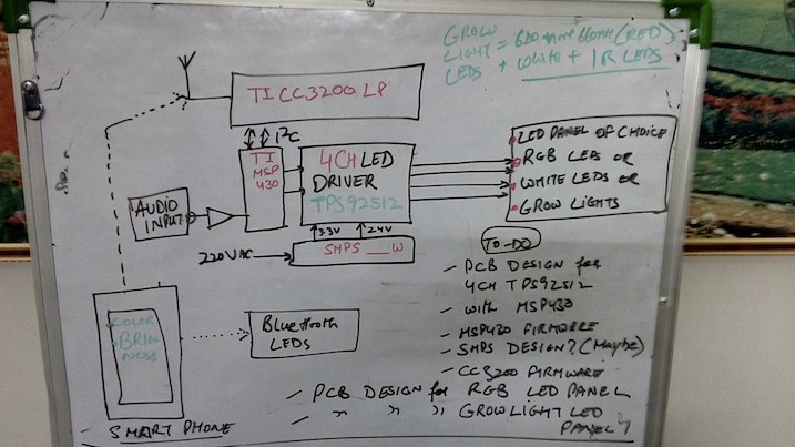
Figure 1: Proposed system block diagram
Driving LEDs and the TPS92512
Just like any other component, a correctly driven LED will improve its lifespan as well as its efficiency. You can also control the illumination characteristics by varying the drive of the device. The LED is essentially a diode, and the forward-bias characteristics (especially Vf) vary slightly from unit to unit as a consequence of the manufacturing process.
Examining the data sheet for Würth Elektronik’s indium gallium nitride (InGaN)-based ceramic-chip LEDs, you can see that the LED’s forward current increases sharply with the forward voltage and is almost linear beyond the knee voltage. The luminous flux also varies as a function of the forward current up to a limiting value. Thus, it would be more beneficial to control the current through the LED when driving it, using a current-control scheme to obtain better results.
Figure 2 from the mentioned datasheet shows this trend graphically where we see forward current as a function of forward voltage and luminous flux as a function of the forward current.
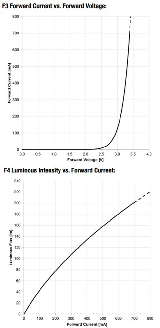
Figure 2: Forward current as a function of applied voltage and its effect on luminous flux output
There are a number of ways to arrange a constant-current source, including the classic LM317 circuit, as shown in Figure 3. The problem is the maximum current you can drive. You can cascade more than one LM317 in parallel, but that is not very cost-effective.
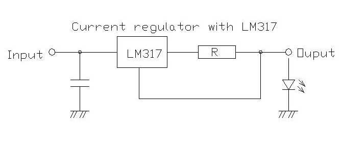
Figure 3: Circuit diagram for an LM317 based constant current source
Alternatively, you can use an operational amplifier/comparator with a voltage reference and then use a transistor or MOSFET at the output stage to perform the regulation manually as shown in figure 4. This works better and is how I usually design power-supply circuits. The major issue with this approach, however, is the amount of board space used, as well as bill-of-materials cost. You end up assembling a large circuit – which is OK when you need to handle a lot of current in the range of tens of amps – but for LEDs this is overkill.
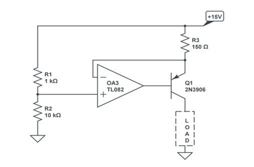
Figure 4: A high side current control circuit using an op-amp
So you need MOSFETs for efficiency but don’t want to make your own module. The solution is a dedicated driver chip like the TPS92512, which has the MOSFET as a switch as well as thermal shutdown, and internal oscillator and pulse-width modulator (PWM) logics for control. Other solutions out there require an external MOSFET switch as well as some miscellaneous passives. The TPS92512 is simpler to use; Figure 5 shows its functional block diagram.
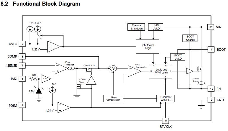
Figure 5: Functional block diagram of the TPS92512
The TPS92512 is capable of driving up to 2.5A; the standard version can operate with a VIN up to 48V. A standard microcontroller with a Pulse Width Modulation (PWM)signal can drive the TPS92512 to vary the output current and therefore LED brightness.
In part 2 of this series, I’ll show you how I built the prototype.