
Project - Building an IoT Light using Texas Instruments Parts
An IoT Enabled Light design using TPS92512 and CC3200
Original Post is at: https://e2e.ti.com/blogs_/b/powerhouse/archive/2016/06/17/designing-an-iot-modular-light
Introduction
In the first installment of this two-part series, I talked about an illuminating idea I had for a project I could use in my newborn baby’s room: an Internet of Things (IoT) modular light. I’ve done the prep, so now let’s create the prototype.
Creating a prototype
As shown in the block diagram in Figure 1 from the previous post, a TI SimpleLink™ Wi-Fi® CC3200 wireless microcontroller (MCU) LaunchPad™ development kit connected to the TPS92512 drives a light-emitting diode (LED) array. I used a 12V switch-mode power supply as the power source and wrote the firmware for the CC3200 using Energia. You could also write the firmware using Code Composer Studio™ integrated development environment (IDE) software, which is my favorite tool, but in this case, the example code and Arduino-like interface accelerated the prototyping stage immensely.
I set up the CC3200 wireless MCU LaunchPad kit with the latest firmware and programmed the kit to talk to a particular topic at the Message Queue Telemetry Transport (MQTT) broker. MQTT is a protocol with very small overhead and allows for a server/client topology to create communication connections over the Internet. Facebook Messenger uses MQTT, and it is one of the more popular protocol projects being tuned to power the future IoT.
For my project, I also designed a small printed circuit board (PCB) that I framed as a Booster Pack™ plug-in module; the result is shown in Figure 1. You can stack a number of these PCBs to achieve the required number of LED drive channels.
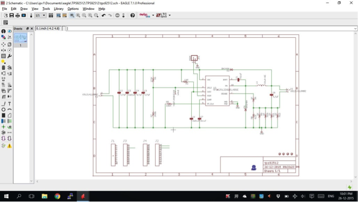
Figure 1: A screenshot of the schematic for the TPS92512 BoosterPack
I was able to fit the design into a 50mm-by-50mm form factor, which would reduce manufacturing costs if mass-produced. Figure 2 shows a screenshot of the final layout which has four mounting holes as well as the BoosterPack module pin conformity.
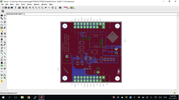
Figure 2: Screenshot of the final layout for the TPS92512 BoosterPack
I used the schematic and layout from the evaluation module as a guide. Würth Elektronik provided the coils as well as the electromechanical parts, which was a big help since they made the footprints for all of the parts available as well. Getting the board design ready was a breeze. Printing the layout and checking the footprints as shown in Figure 3, confirmed that everything was indeed in order.
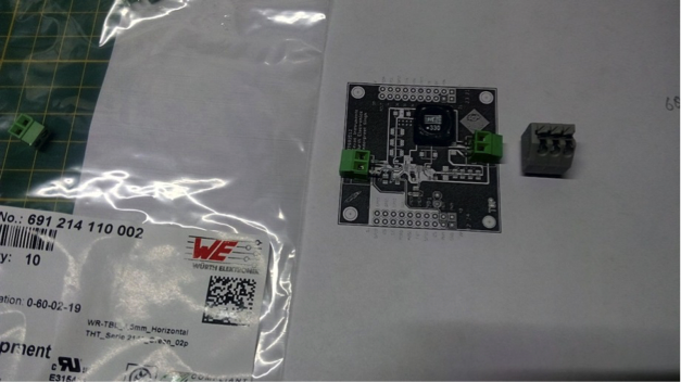
Figure 3: Footprint verification via 1:1 paper print of the layout
The Web client design
With my basic understanding of HTML, Code Composer Studio IDE and JavaScript®, I was able to create a simple user interface (UI) for my project. The idea was to create buttons in a web interface and then use JavaScript to send the commands via MQTT to the broker and finally to the IoT light. I used the Paho library in JavaScript and performed a bit of cosmetic surgery via Code Composer Studio to create a webpage that looks nice; Figure 4 is a screenshot.
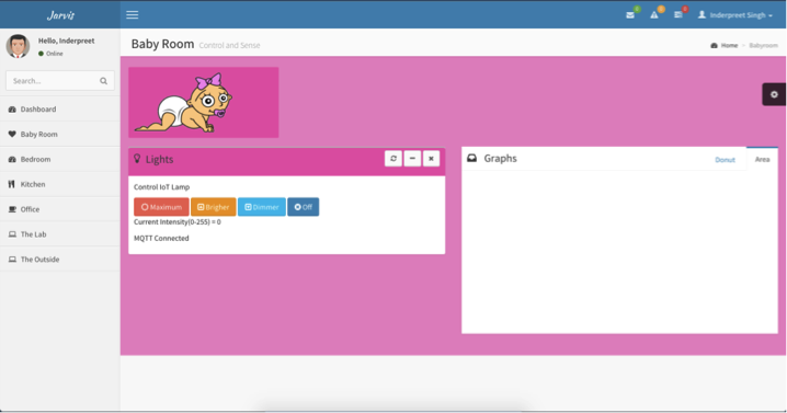
Figure 4: The live webpage for remote control
I kind of went overboard with the home-automation front end, but you get the idea. I wanted a look-and-feel I would be willing to pay money for. In the end, four buttons was all I needed and they worked out pretty well. The page uses Twitter Bootstrap, which means the same webpage will look different on different screen sizes.
The love and romance
I had worked out the technical details of the project, but it was more or less a science project. The real evolution came when my wife suggested that I turn the prototype into a real product for our own use. We were expecting a baby at the time and she requested a room light whose brightness we could control remotely. The same light would be usable as a room light, a night-light and a midnight-diaper-change light. Instead of 3-D printing an enclosure or something, I decided to recycle an old LCD monitor, some glass and a birthday card from before we were married. The romance was still alive and it was time to light things up. The manual layout of the components inside the enclosure is shown in Figure 5.
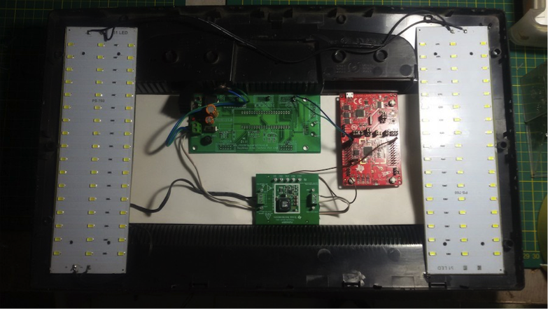
Figure 5: Various modules laid out in the recycled PC monitor
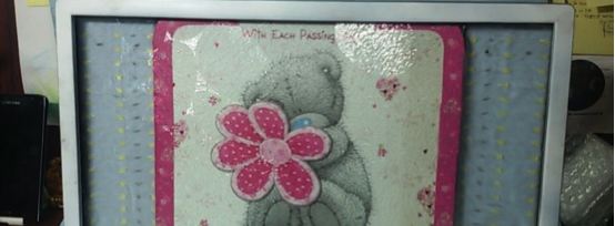
Putting humpty dumpty together was fun and the finished product is shown in Figure 6.
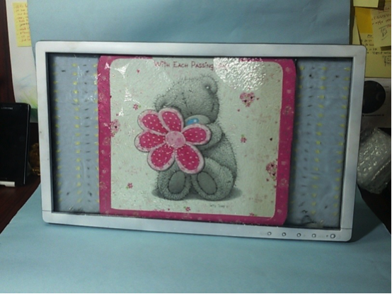
Figure 6: The final product
The final product is not particularly a product so much as a piece of technology fused with a personalized artifact. Our baby currently enjoys staring at the final outcome above his crib and we are thankful for it.
Future work
I am currently working on creating a grow light for indoor hydroponic farming based on the same concept, which thus represents an additional application. Security was never important for this demo but is crucial for IoT products, so I am working to implement a more secure solution. I am experimenting with Raspberry Pi as a local broker, as well as considering porting the entire web UI to the SimpleLink Wi-Fi CC3200 device itself. Both solutions are viable but cannot be an IoT solution, since they will no longer require an Internet connection nor be accessible over the Internet.
Conclusion
This project is a proof of concept but with a personal touch. I have had a lot of requests from friends to make one for them. So far I have declined, but maybe in the future I can provide a Phillips Hues alternative. The important thing about this project is it proves it is quite easy to come up with an IoT prototype quickly and easily with the amount of resources available. Thanks to Texas Instruments, Würth Elektronik and element14 for their support. The future is indeed bright.
Additional resources