
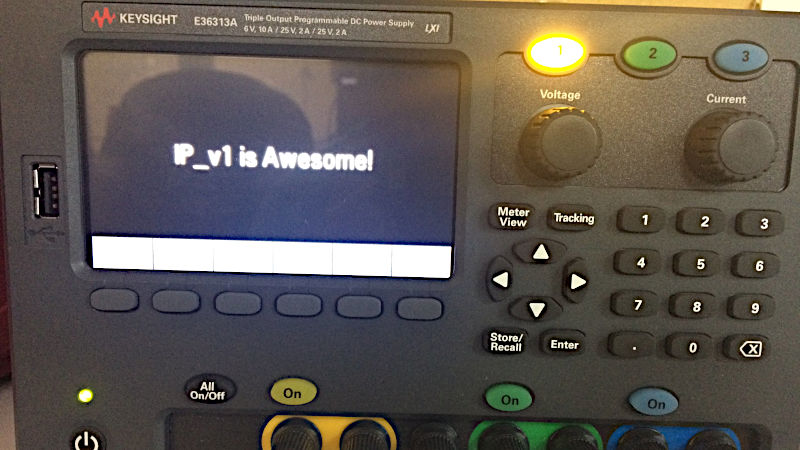
Review - Keysight E36313A Triple Output DC P.S.
Guts and glory of the Keysight full featured Lab Power Supply
Introduction and key features advertised and to be reviewed
I received the Keysight E36313A in the second week of January 2018 and there is so much this thing has to offer that I am still catching up. This review revolves around testing the Keysight E36313A for Embedded Development and Test. At the time of this writing, I am still experimenting with the supply and the review can be considered a first impression of sorts for each application. I am yet to dive into 4-wire measurements and battery drain tests since these require a little setting up.
Instead of using the benchvue software, I was able to write a python app for controlling the PSU over a network. The idea is to be able to script a testing routine and then let the PSU do it’s thing. Set a voltage and read the current etc. I ended up with a web app which is totally unnecessary but I will be sharing it this week once I have the code polished up a bit. Here is the part installment of the review.
Box contents and First Impressions. Build quality.
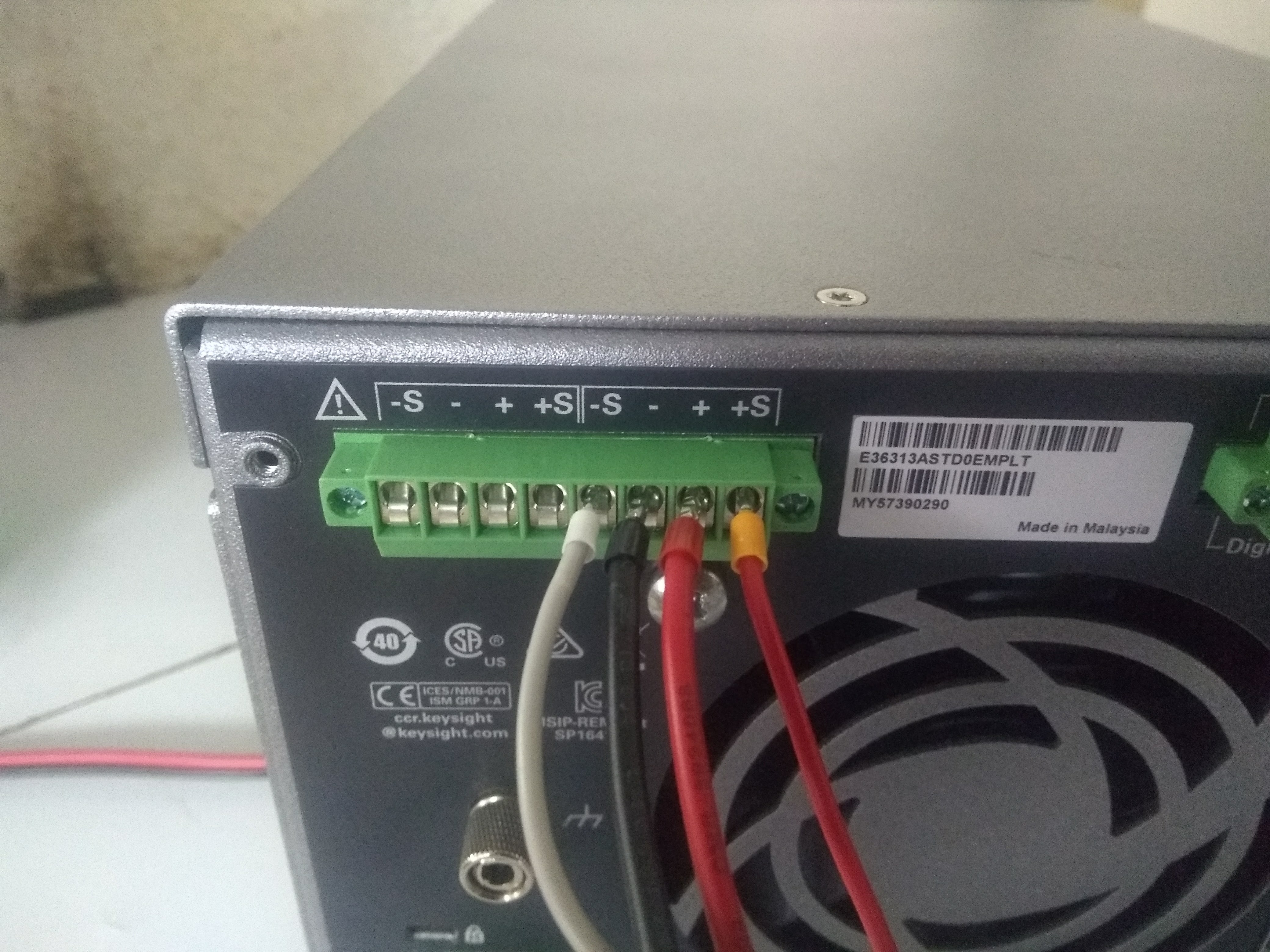
The box arrived with good packaging and the power supply was safe and sound. It was accompanied by a small box with a basic starter guide, calibration certificate, and a power cable. There were some screw terminals as well that fit at the back of the PSU that we will see in a bit. I was surprised at the absence of any banana cables etc. though. Fortunately, I had received some thanks to Tariq and the team at e14 as a reward for a project14 win.
Here is a short video of me unboxing the PSU… unedited.
This may be unnecessary to many but we need to go over the supply specs once. The E36313A is technically a three output PSU but there is a catch… take a look at this.
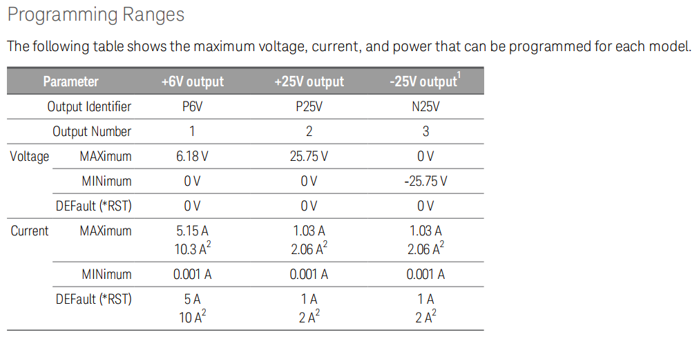
The first output ranges to around 6V max but can supply currents of upto 5 Amps. The other two outputs are ranged to 0-25V and -25-0V ? Well not exactly. Taking a closer look I found this.

For the E36313A, the first output is a 10A rated one and the remaining two are 2A. For this particular model, the outputs are isolated and outputs two and three can be used in series mode for a larger voltage output range or in parallel mode for a better current capability. More on this later.
As we will see, output one gets it’s own little PCB which clear in the teardown photos which means there is a lot of muscle under that hood.
Shortly after the unboxing, I tried to see if the portable handle on the device was up for the job and the result was a yes but barely. The plastic cover on the side clip broke off almost immediately BUT the handle stayed in place. So much for cosmetics.
In order to talk more about the build quality, we must delete deeper into to the little grey box… Teardown!
Teardown
We were informed by Element14 that our warranty would be honoured even if we rip this PSU limb from limb. So then… why not?
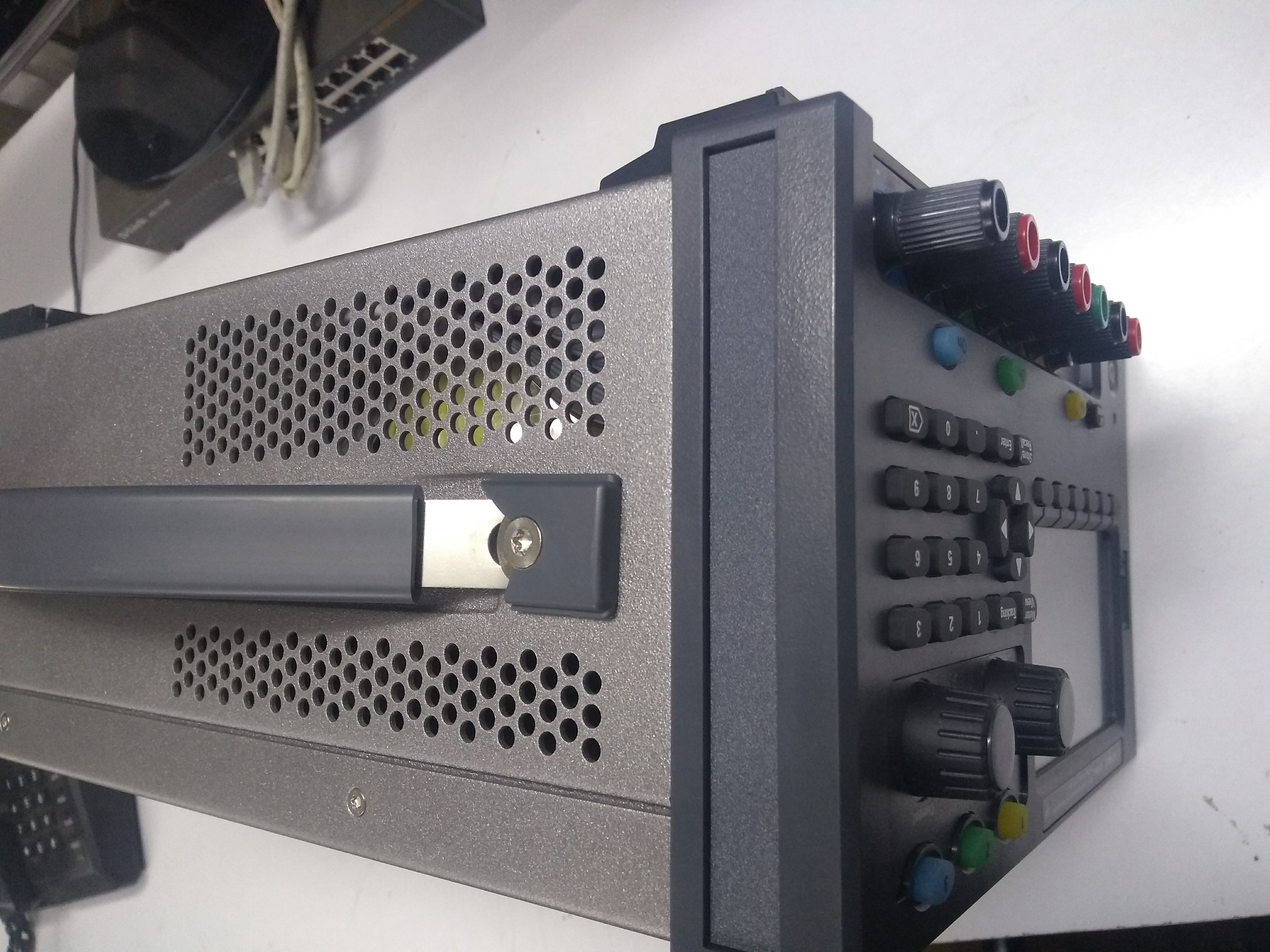
The PSU has a top hatch which can be removed to get access to the internals BUT that’s not it. Here you can see the +- 25V power supply board which also has the ethernet and USB controllers. This board will not pop out because it also connects to the from panel using a connector. For that there are four hidden screws that need to come out.
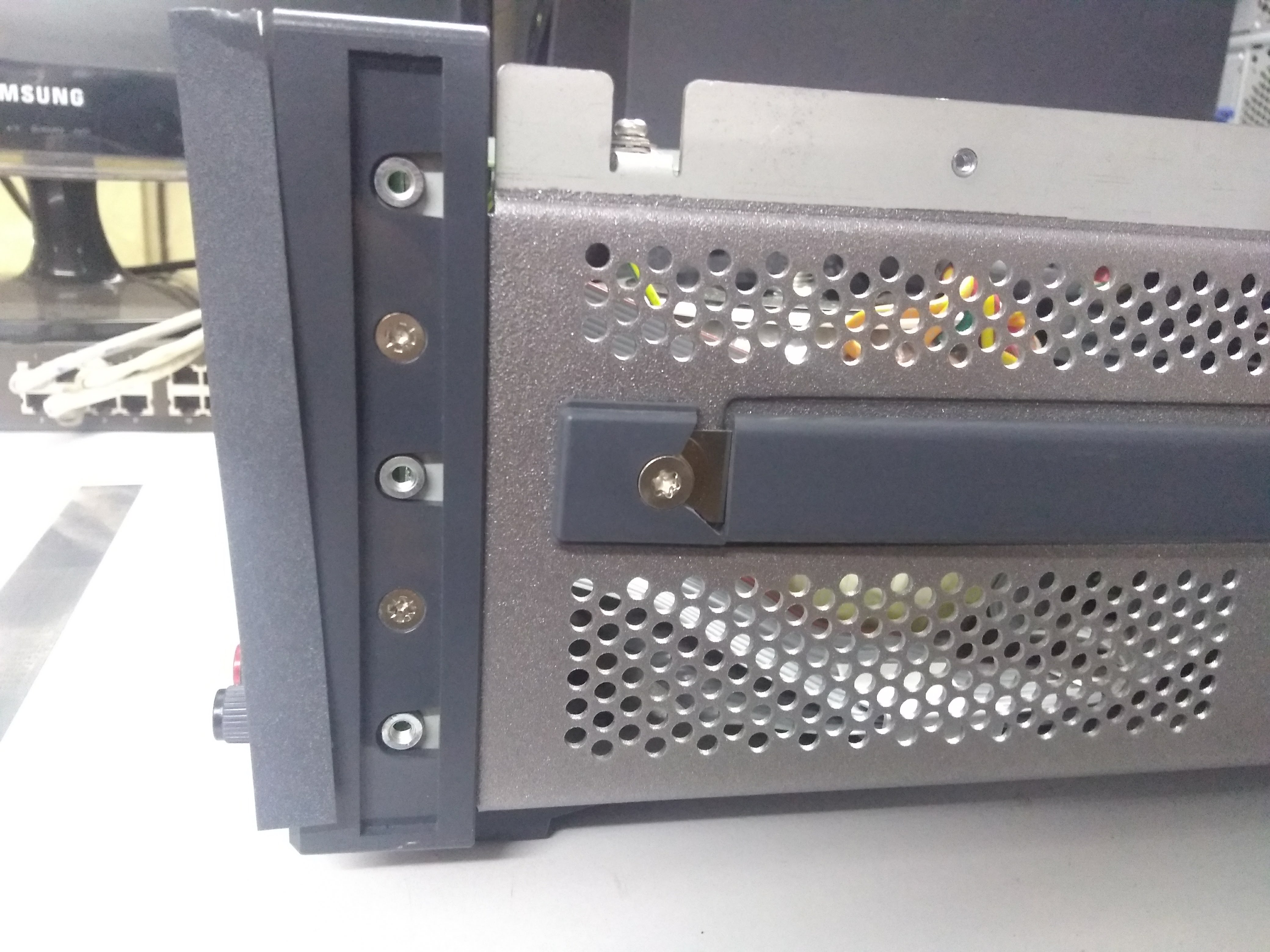
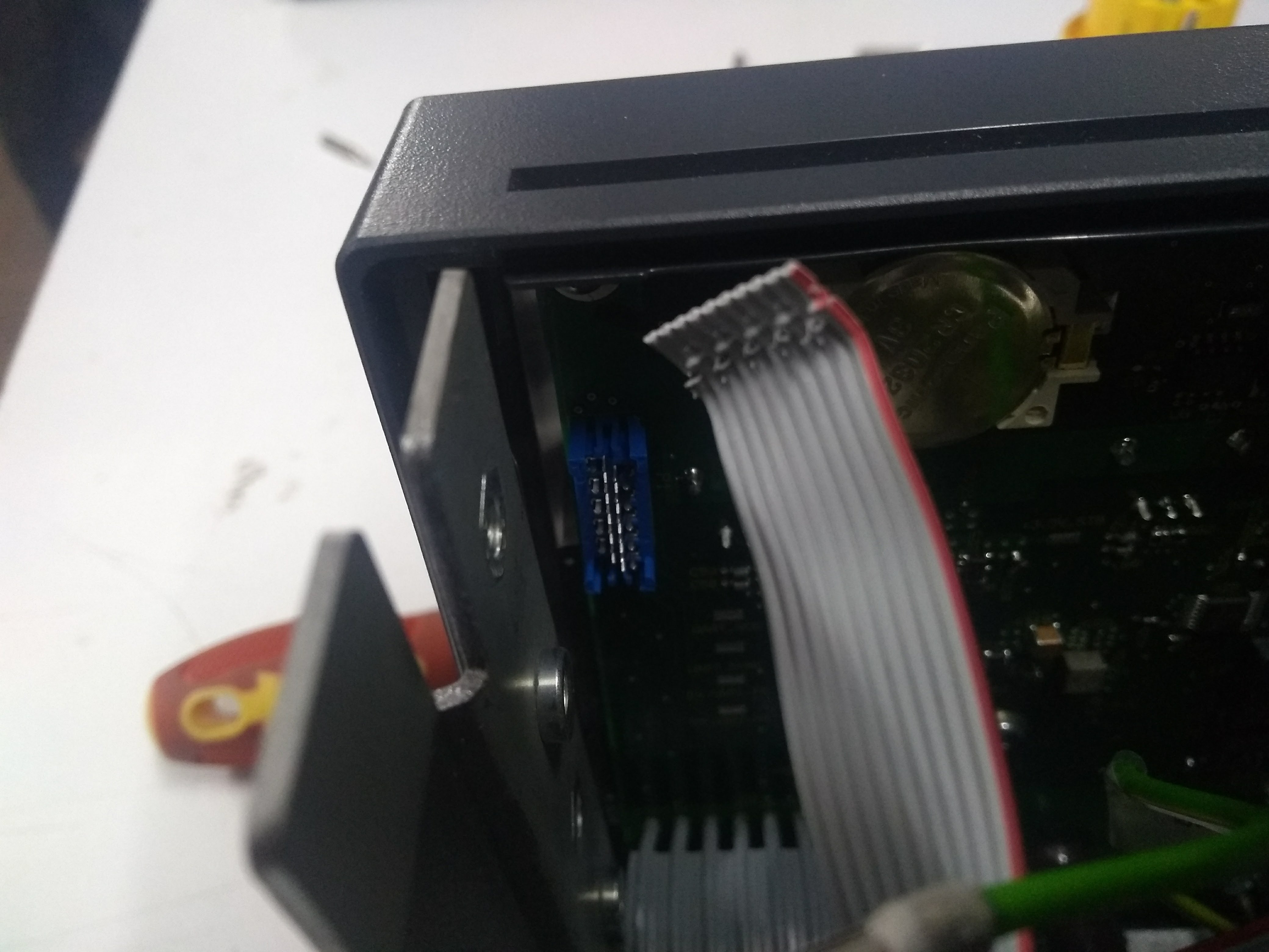
Take them out and you now hit another snag. There is another cable that connects the front panel but do NOT yank it out like in the images below.
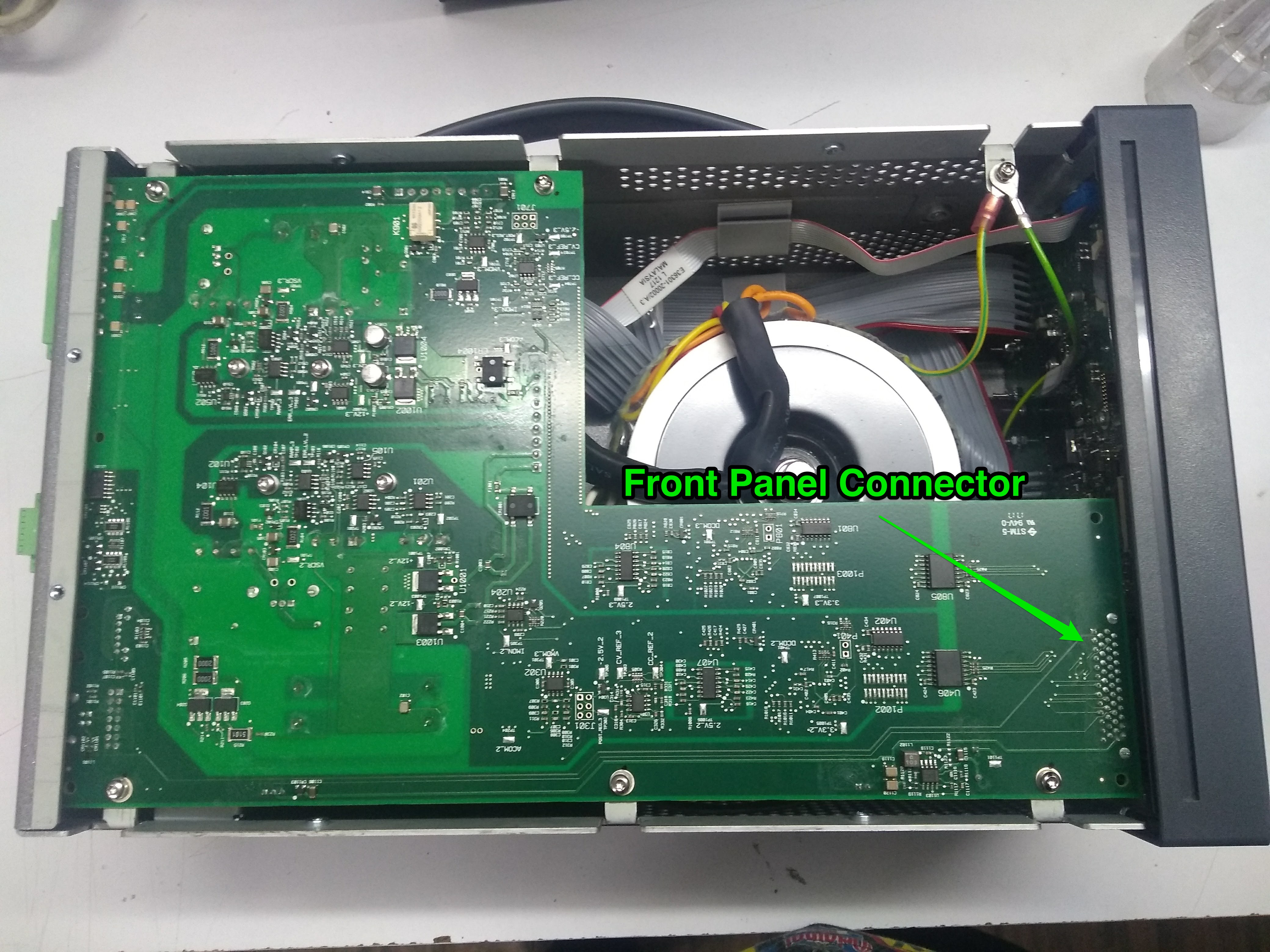
Once you get those out, you get access to the back of the front panel. Here it is…
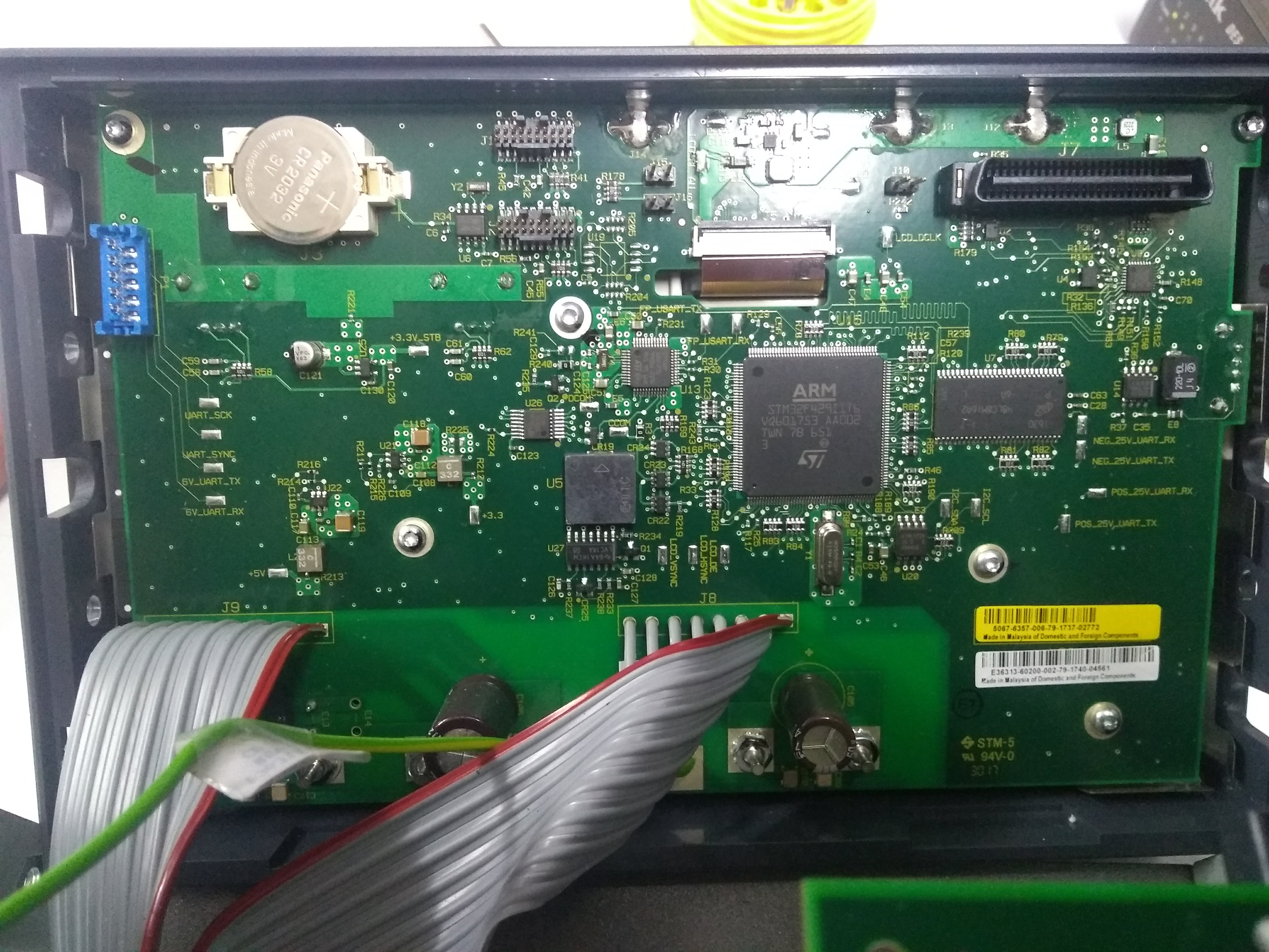
The front panel is powered by an STM32F429 which has the graphics driver hardware. Element14 gave some of these away in a recent roadtest(insert link here) and they were awesome. There is an RTC battery if anyone is wondering and there are mostly ribbon cables in there which is good for wire management however not so great if you twist and break these internally. Taking a top view look, we can see the toroidal transformer that is the heart of the design. Less EMI, cleaner output and battery efficiency and key sight have spared no expense here.
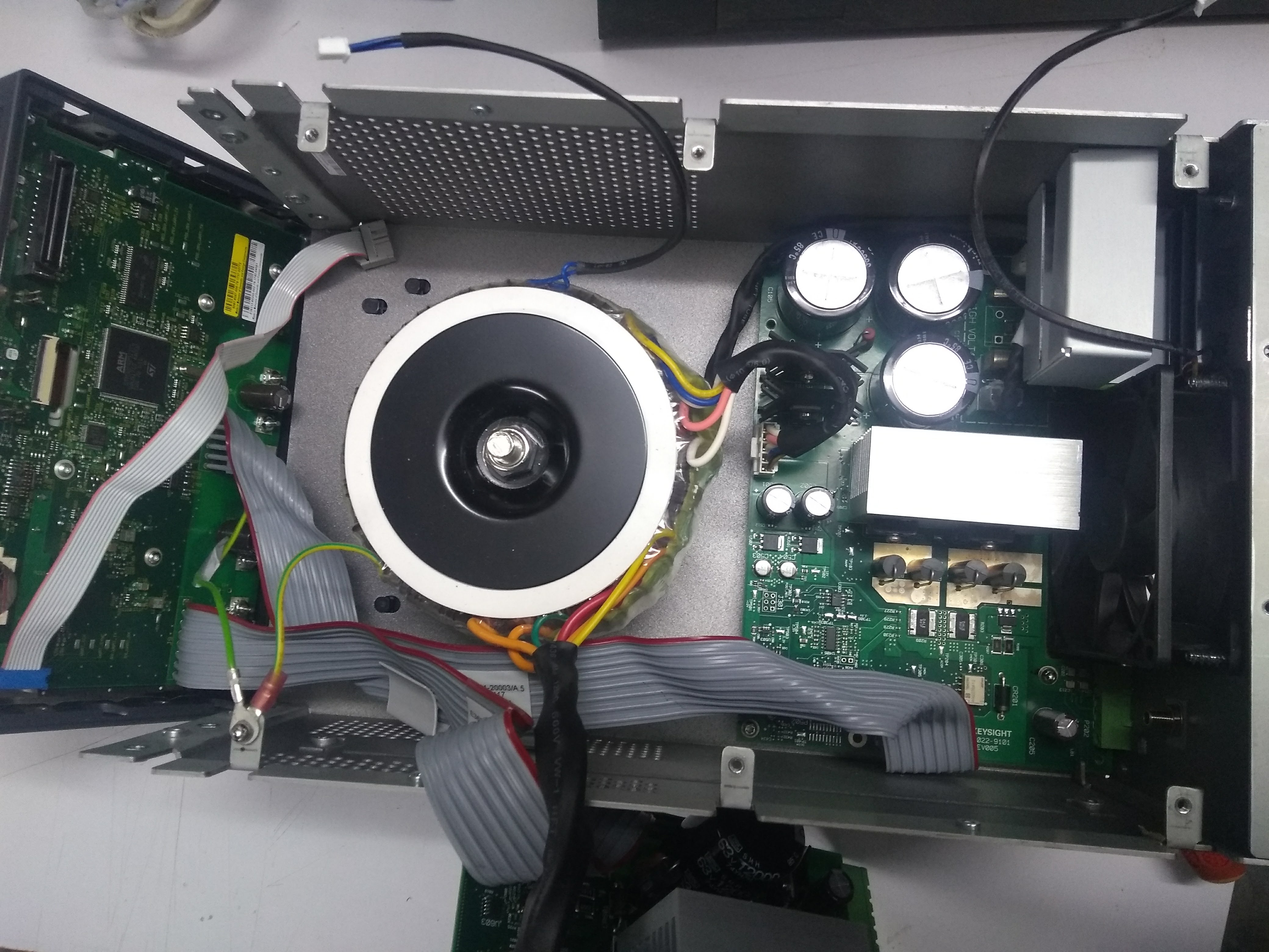
That other board seen on the right is the 6V 10A supply. You can see the MOSFETs and the big filter caps for that extra clean output. I am guessing there is a temperature sensor in the toroidal to detect thermal issues.
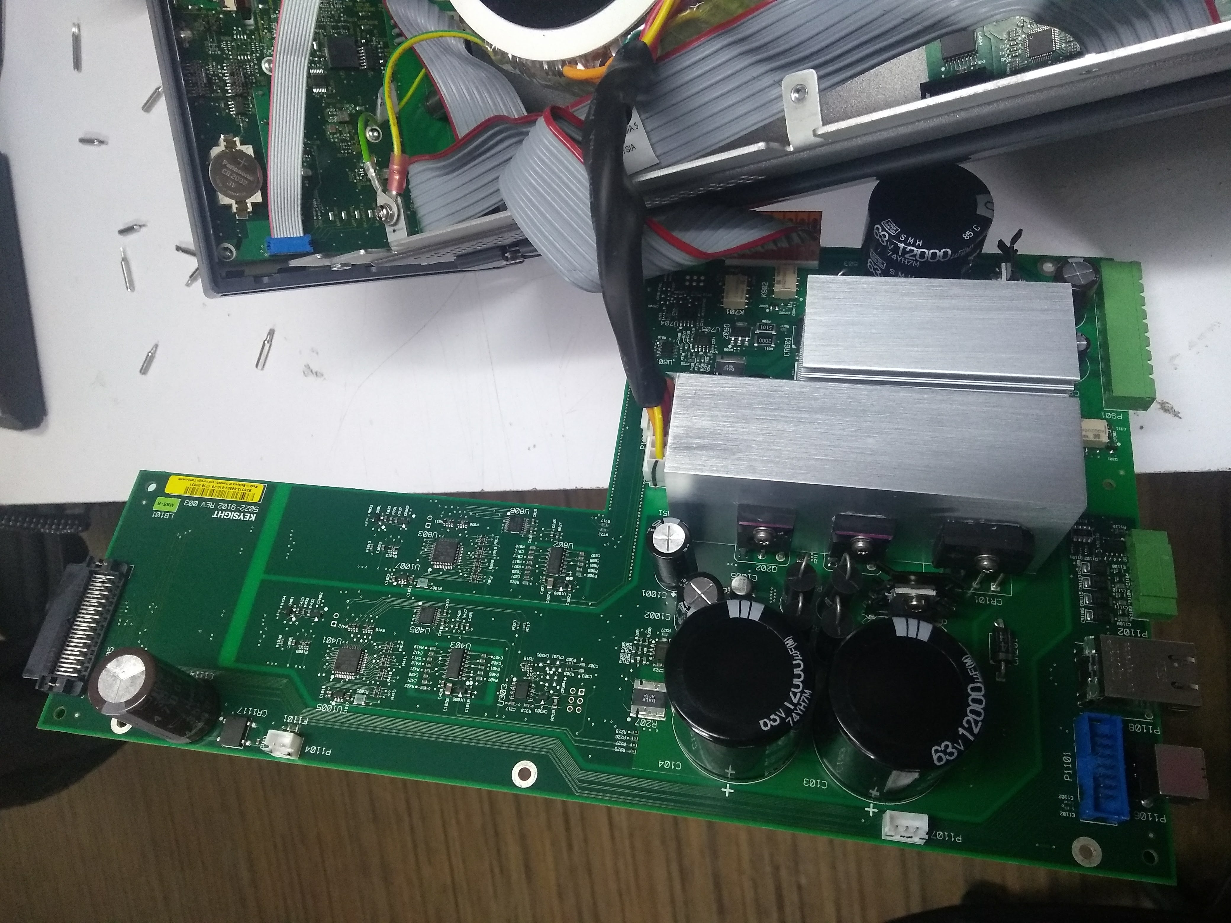
Here is a closer look at the +-25V board. You can see the rectifier and MOSFETs and the connector for the transformer input and there is also a ribbon cable taking the output to the front panel. The connector seen on the left takes the USB and ethernet signals to the main processor.
Every channel is controlled by an STM32F103 or something which makes sense. The master processor on the front panel acts as a master and probably talks to the others over I2C. There are current sense circuits all over the place which is probably why the front panel has a high resolution metering circuit. Set the voltage to 5.00V and you will get 5.01 and the display will accurately tell you what the output is.
I did not dismantle the front panel since I don’t expect to find much beyond some expensive op-amps and voltage references. Also, I am still processing the teardown video and won’t get it done anytime soon. It takes a lot of time and lot of criticism so I am not in a hurry.
The proceeding sections contain the tests I performed on the PSU and the corresponding findings
Manual measurements and data logger- Measuring power consumption on the HaD SuperCon Badge
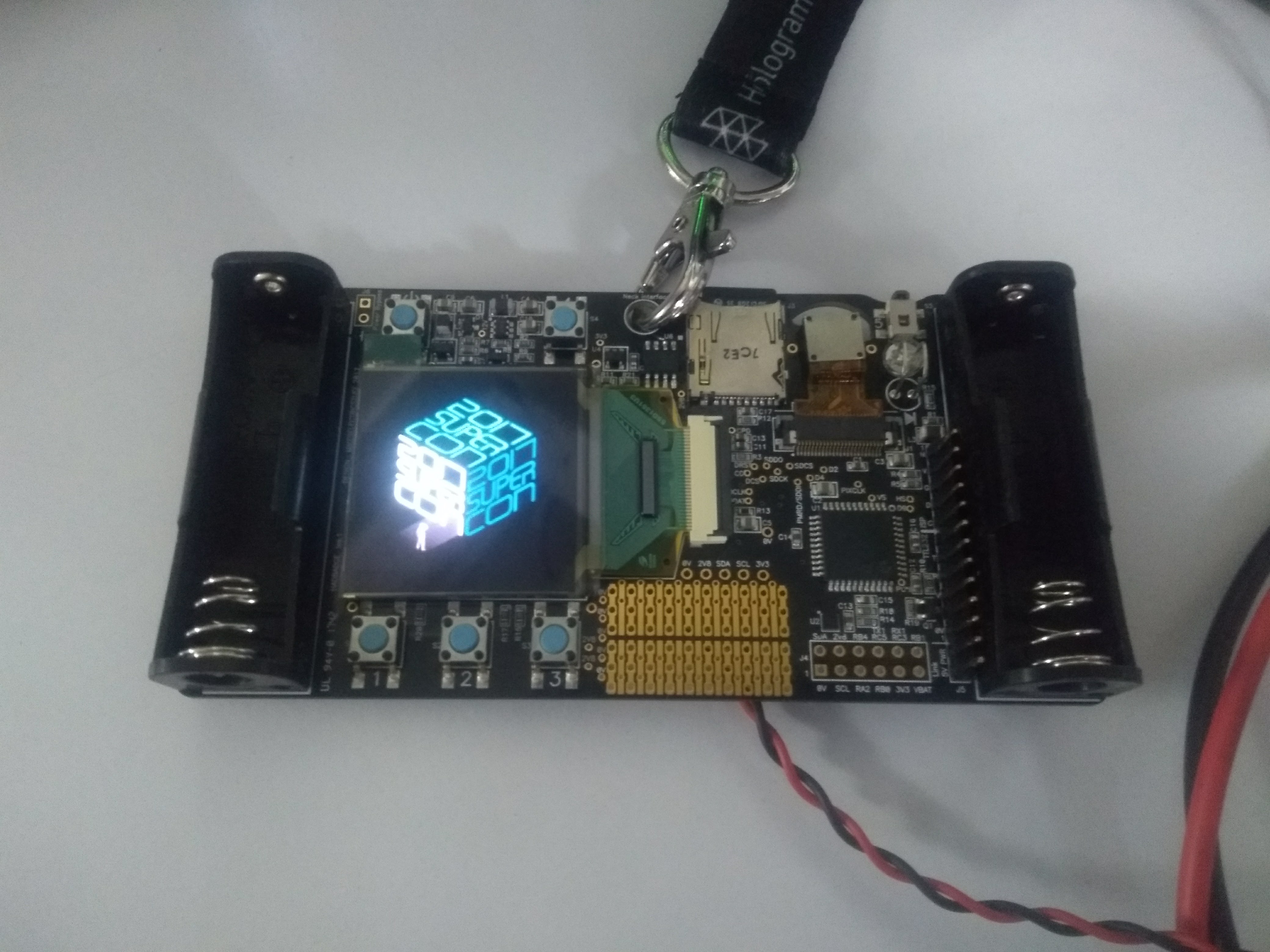
Since the E36313a is advertised to have a current measurement resolution, I decided to test it out. The supercon 2017 badge is designed to run on two AA batteries and features a lot of cool stuff such as a Camera, an OLED display and can do cool stuff such as image effects and what not.
Boot up and shutdown analysis
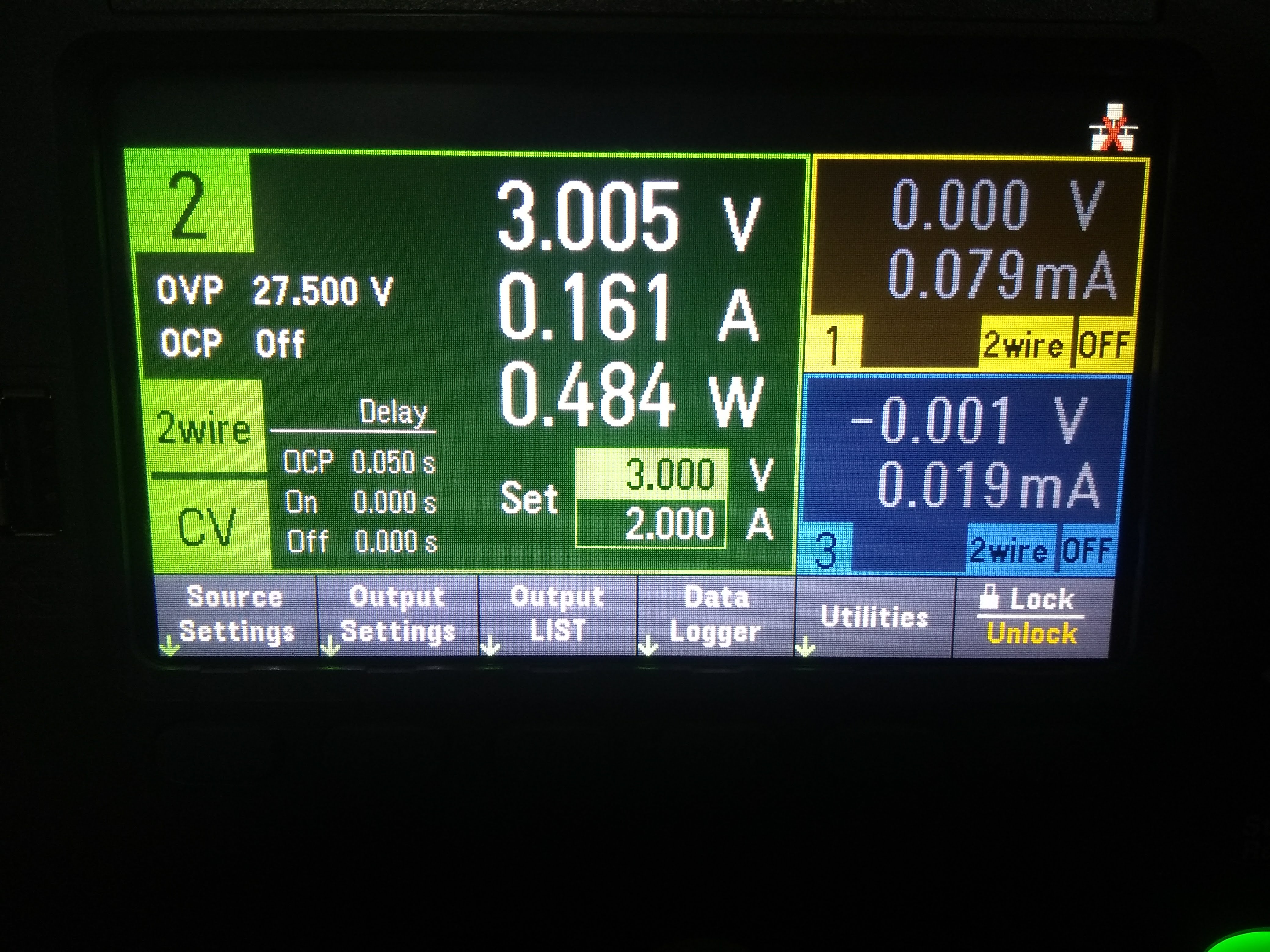
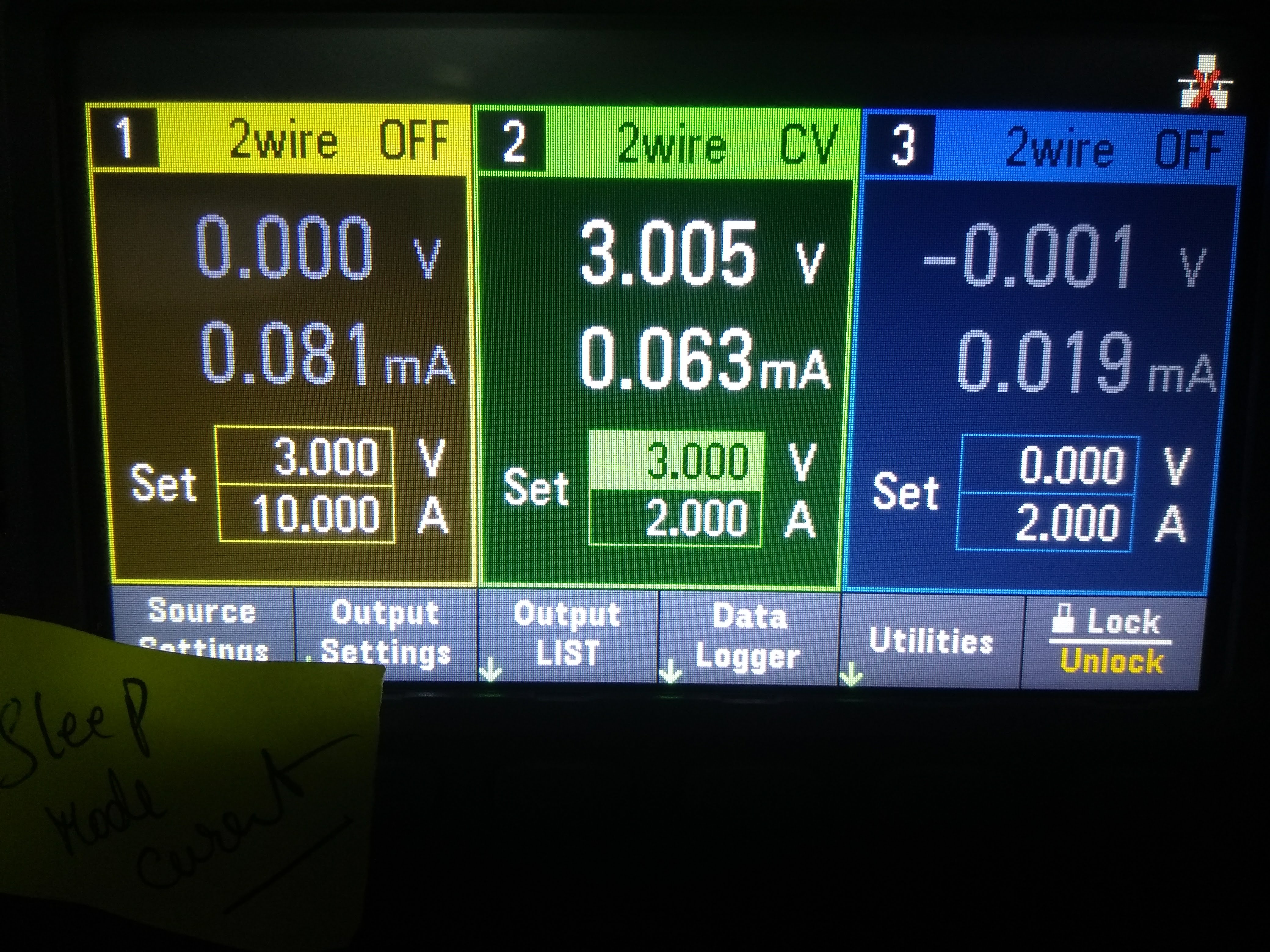
The SuperCon badge was connected to output 2 and set to 3 volts since it is designed to be powered from two AA cells. I configured the data logger to capture 30 seconds of V, I and W. Here is what I got.
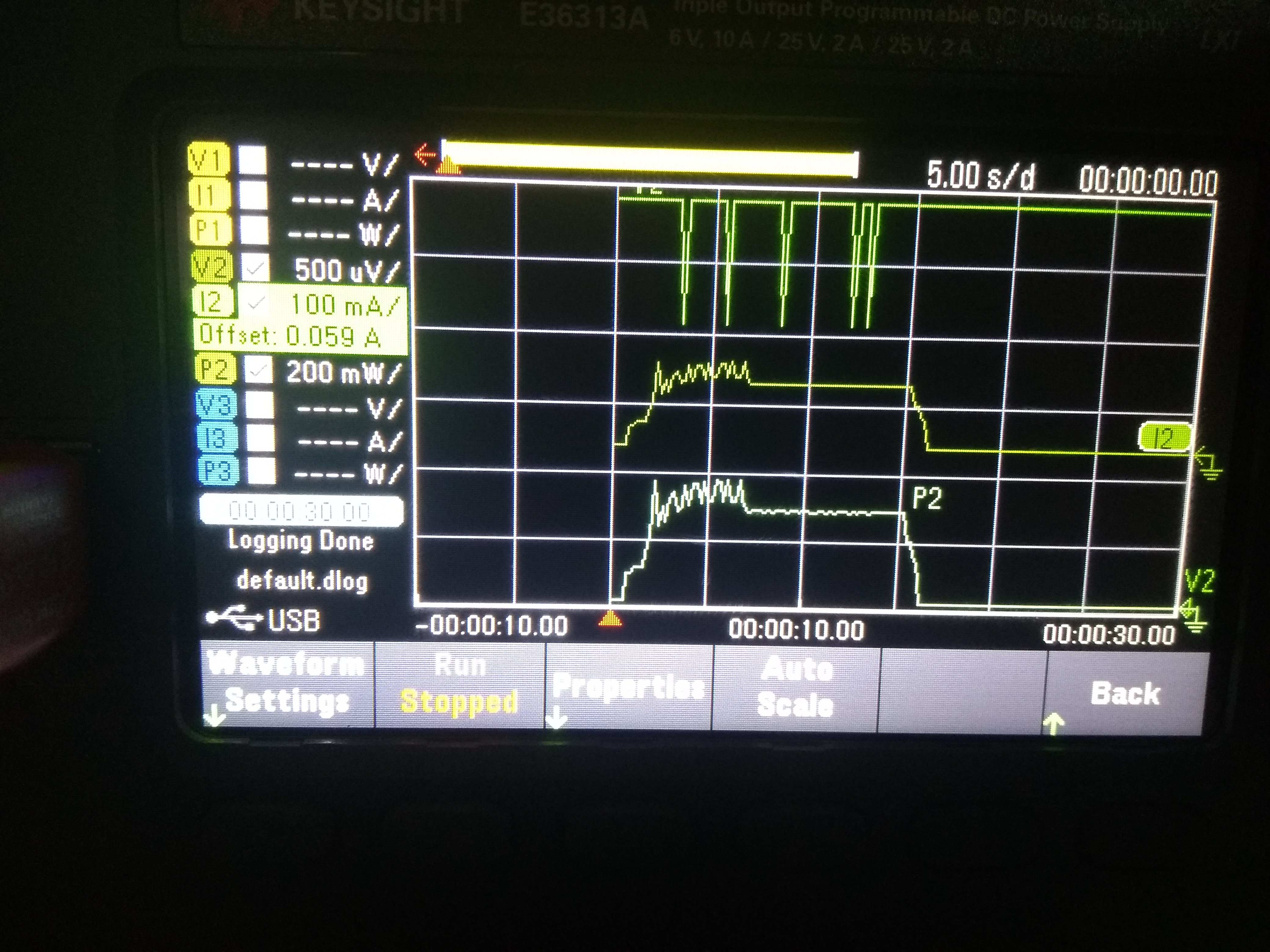
The graph shows the board powering up and the peripherals starting up as indicated by the current graph. There are spikes and then finally settles down. When I press the shutdown button, the current ramps down and stays there.
This is useful to understand processes that cause current spikes and may have a detrimental effect on the battery life. Since the data can be exported to a csv, here is a graph of the same data.
![]()
The inbuilt DMM Is pretty useful as well as we will see in the next sections.
Camera power consumption test
After power up, I checked to see if the camera and consequent power on were consuming too much power. Here is a graph from the data.

The metering mode captured the power consumption of the badge with the camera and LED ON.
Not bad
The camera and LED do take up a bit of extra current and it can be easily be analysed using this PSU. One thing to note is that the USB data logger is not continuous. It captures chunks and I really wish I could do a continuous capture till a stop button is pressed.
Active and sleep mode power consumption analysis - uAmps in the field!
The badge in power down mode will have the input regulator in sleep mode. How much power could it consume?
Yes. The microamp range works wonderfully and the wattage calculated is a handy tool to predict the life of the embedded system. Once powered on, the device sucks up a bit more power.
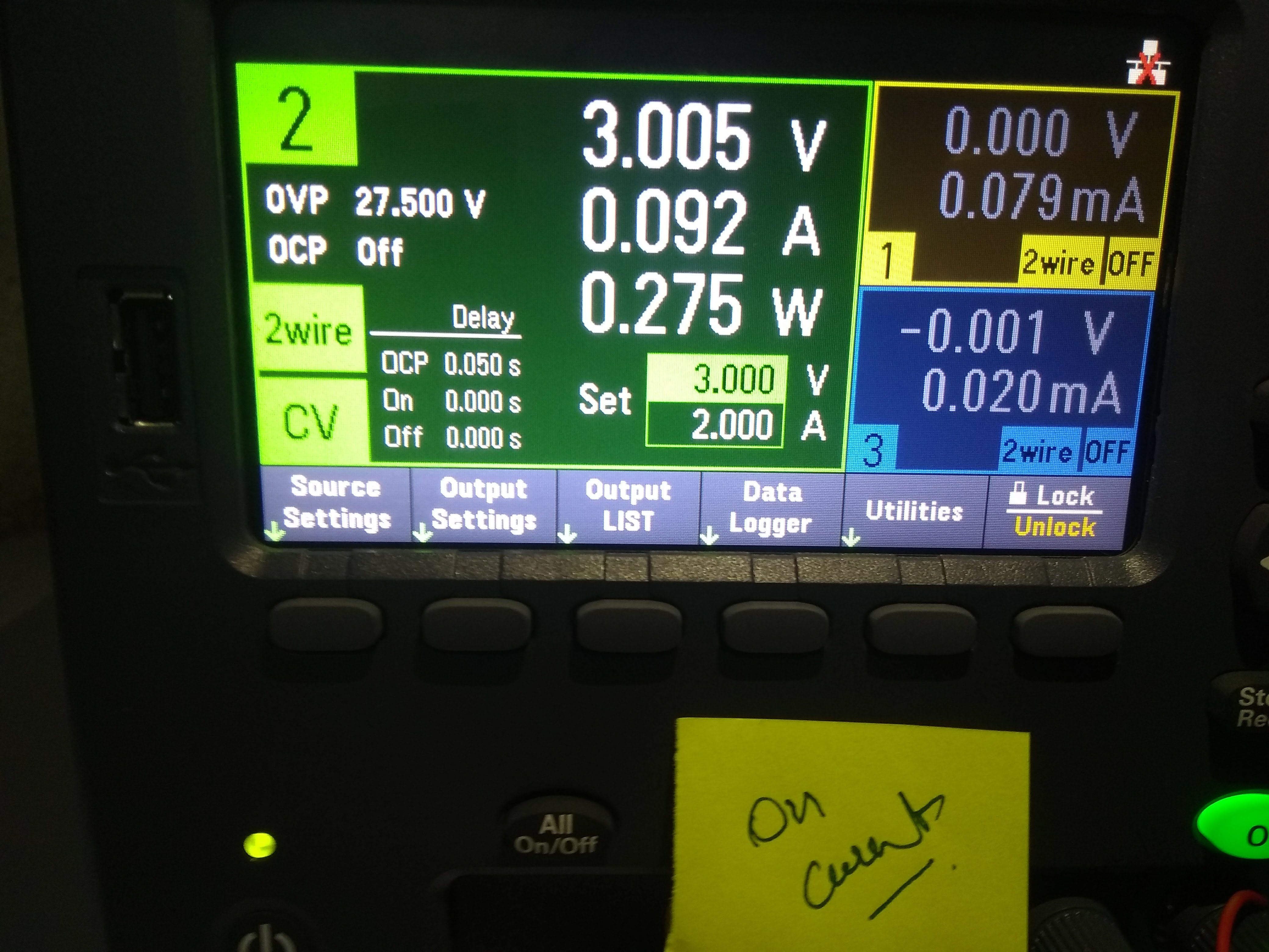
No more fumbling with multimeters and current sense amplifiers. This was totally unexpected and a pleasant experience.
Manual measurements- ESP8266 Measurements
This one is on my to-do list. I want to be able to measure current when a sensor transmits data in an intermittent fashion.
Ripple Noise Measurement for the PSU
I was not able to do a successful ripple noise analysis but rather found something else while I was testing. Not sure why it is but it seems like noise popping in when I connect the scope ground probe to the PSU.
I am still investigating this but I think it is the switching noise from the PSU itself and will disappear if I connect a load. Any thoughts on this would be welcome.
A little Accuracy Testing
I tested the Keysight’s onboard DMM against an IDM 99 III and the results are remarkable.
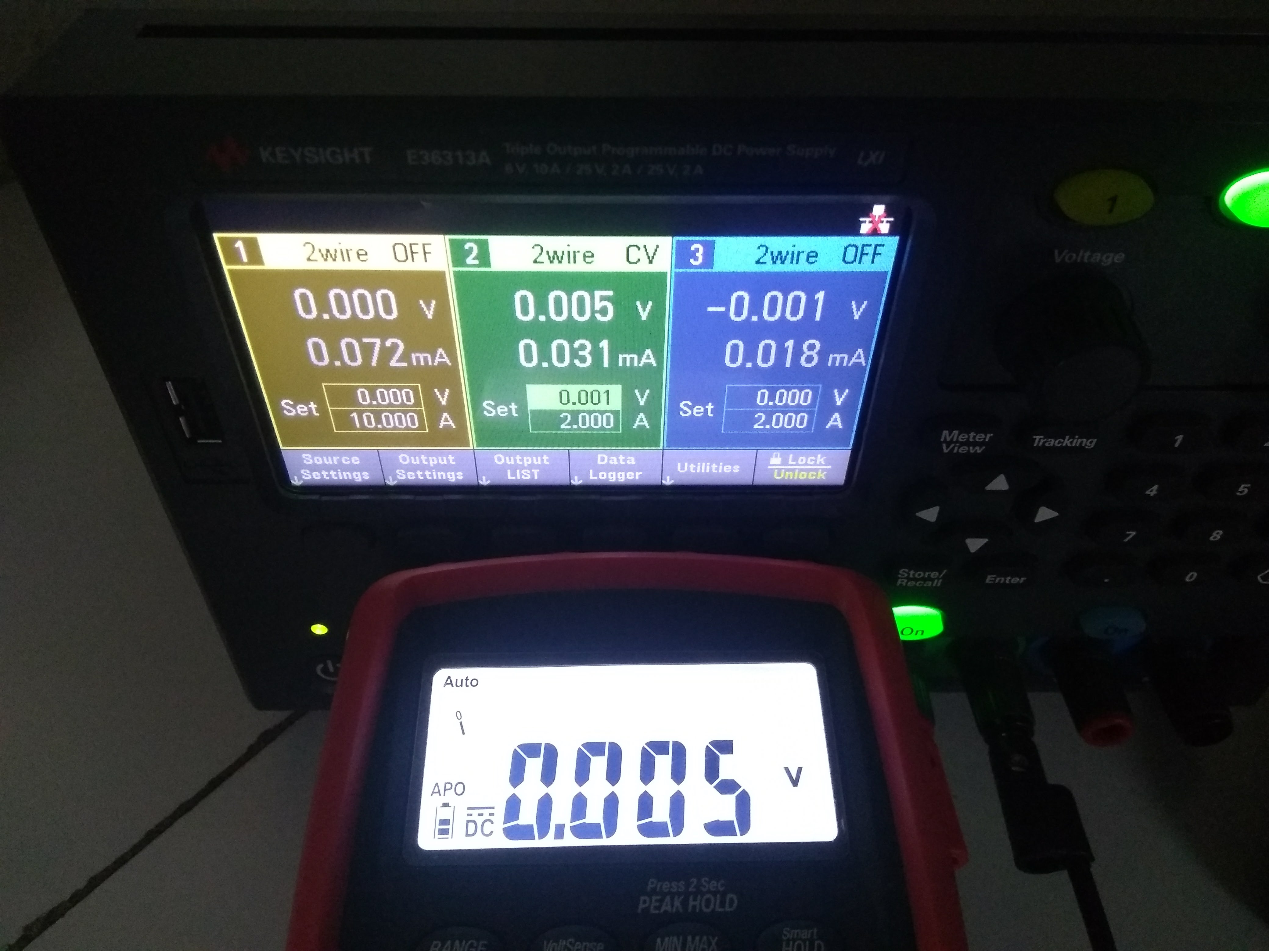
Funny though since I set the voltage to a different number and if it can measure the voltage, why not correct it?
Inrush Current Measurement - // TODO Select Device
This segment is still in a To-Do state since I am yet to find a suitable candidate for the test. I am looking at DC motors for now and am setting up a 25A H–bridge using the Infineon Board I got a few years ago.
The idea is to monitor output regulation on the PSU and see the effect of connecting a large DC load at the output of the high current output.
4- Wire Measurement Introduction
Typical 4 wire measurement or 4 wire sensing is more commonly known as Kelvin Resistance Measurement. When measuring very small resistance, the resistance of the connecting wires becomes a potential source of error. The idea here is to supply a constant current such that the voltage drop across the unknown resistance follows ohms law and also becomes a constant value. Next, the voltage drop across the unknown resistance is measured using a voltmeter such that the measurement current flowing through the leads is negligible. This voltage is then used to calculate the accurate value of the DUT.

4- wire measurement- What the E36313A Offers
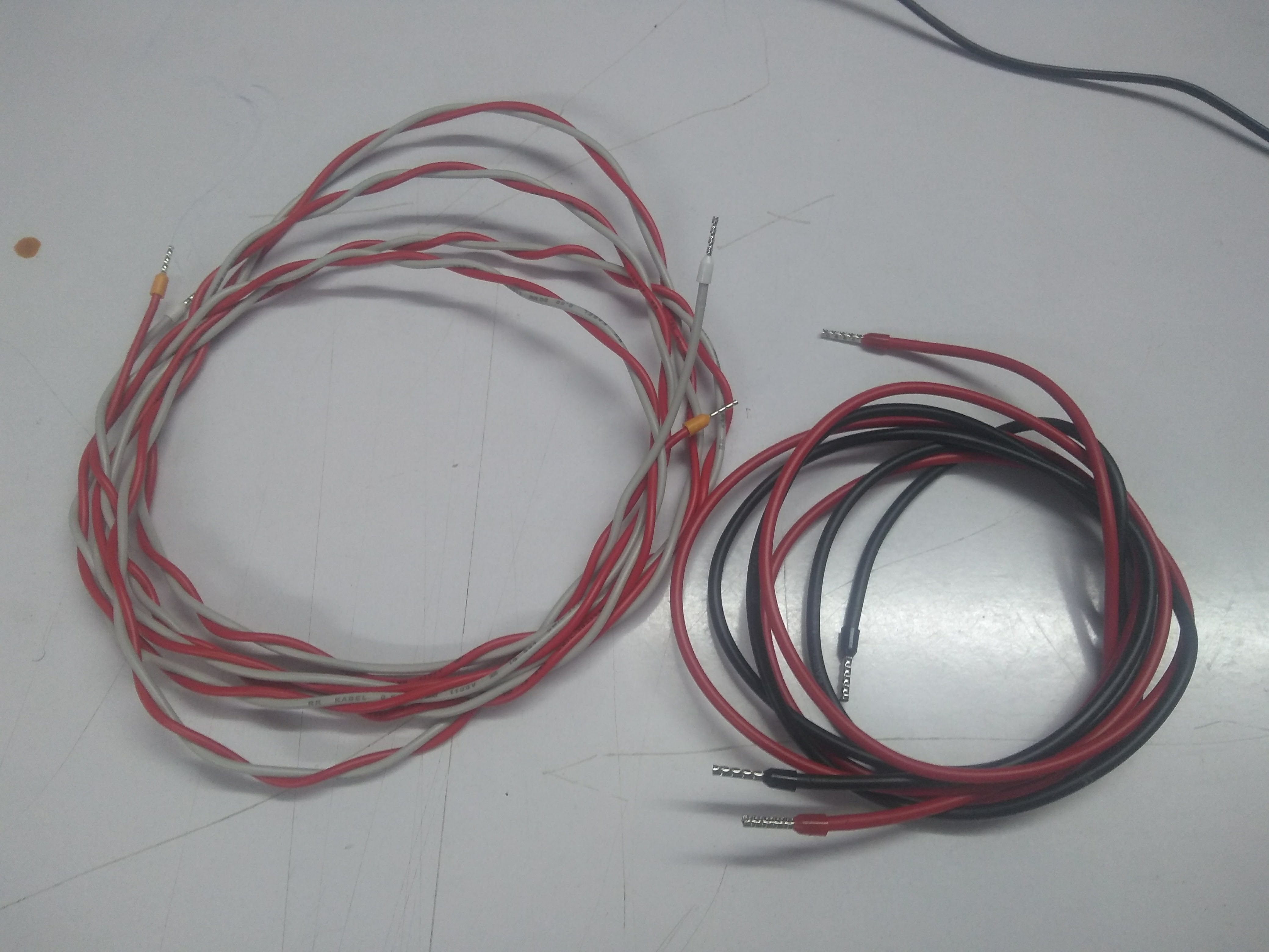
The E36131A is capable of 4 wire remote sensing with the details available on page 32 of the user guide.

Since the PSU itself does not come with any kind of test cables, I had to fashion my own.
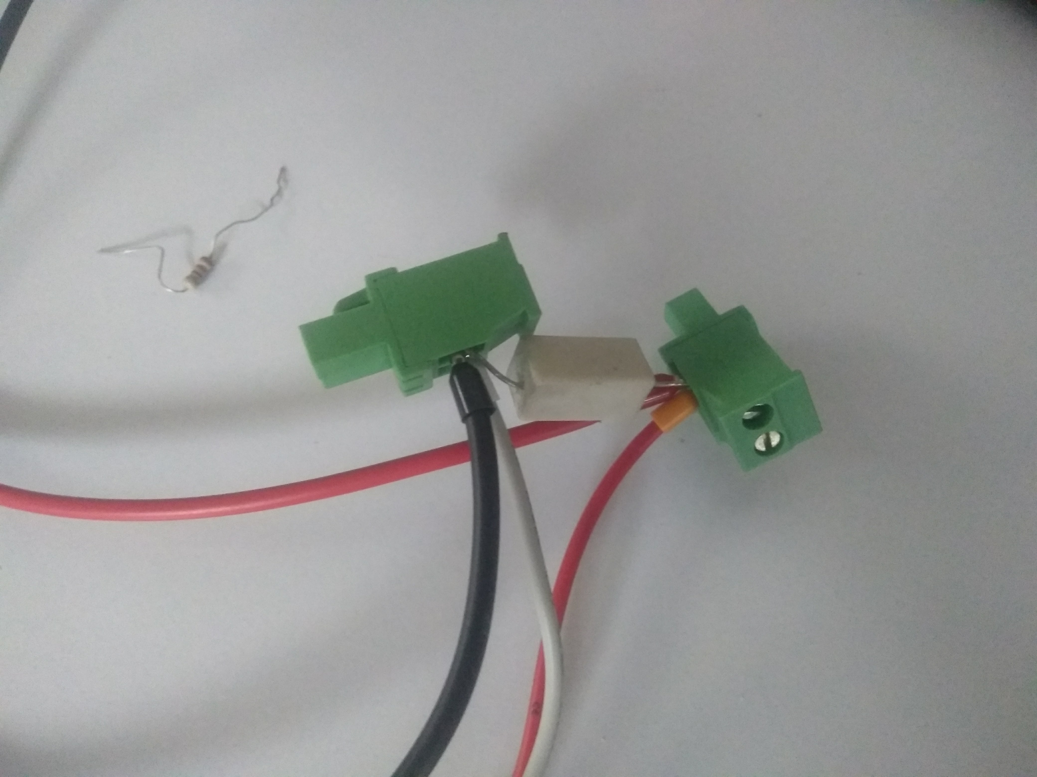
That is a 3W resistor… or it was before it’s little accident.
I was unable to create a case where the difference was significant and errors could be observed hence I have some smaller resistor values and higher wattages order up to take a re-test.
Introduction to Ethernet Connectivity and VISA standard
The VISA standard allows for instruments to be controlled over an RS232, USB or Ethernet connection remotely. In this case, the instrument be controlled via a software. I am not going to go into VISA standard here but suffice to say that it is such a standard standard that languages such as python have a library for it!
For others who have more experience with software such as LabView, the PSU can be controlled that way as well.
This begs the question as to why that would ever be required. For starters, the data logging capabilities are limited hence remote logging could be a potential application. In some cases this could even be clubbed with the 4-wire measurements to determine efficiency of a system and losses incurred over a period of time. The E36313A can pass for a DMM so this makes a lot of (remote) sense.
Another application is scripted outputs. MPPT or Maximum power point tracking algorithms vary the current drawn by a device when charging such that the maximum amount of power is drawn. To test such setups, either you can run around with a solar panel in hand, in and out of the shade OR you can program a PSU to emulate a solar panel generating varying voltages and current limits. A lookup table could be used to simulate an entire 24hour cycle for say a lead acid battery charger in the field. This is the premise of my test.
Basic Remote Control of the PSU with Python
OK. I am going to say it out loud. The benchVue pro software is not cheap. And for instance where a custom yet simple requirement is at hand, its better to make your own software.
The first thing to do here is install the python library from https://pyvisa.readthedocs.io/en/stable/
Complete instruction are already given BUT I also installed the keysight connection expert Software and keysight IO library suite to boot. Here is a simple script to get you started.
Yes. It is that simple. So what do you get?
More advanced control - Data logging to CSV or PLOTTING IT IN REALTIME
It turns out I went overboard and made a webapp in Flask and then I went on to create a dashboard kind of thing and then moved to create a bootstrap scaffolding and at this point I was far off from what I wanted to do. Anyway I did get the basic setup ready so what I need to do next is finish the backend code to control the instrument.
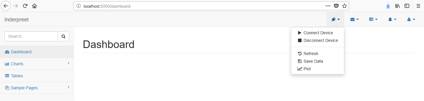
I am aiming at the ability to set and read the outputs and plot a graph of the same. Thats it! ( I keep telling myself so that I might just listen.
Characterising an LED using the PSU. Is it possible?
This is my last todo where I vary the constant current remotely and then read another sensor(an LDR or photodiode) reverse current to obtain a graph of current vs illumination
Conclusion
One thing is for sure that this is not your run-in-the-mill PSU. There are a buck load of features and possibilities that are not completely documented. I am still processing the functionality and but so far I am in awe of what I have seen.
TO-DOs:
-
InRush Current Analysis.
- 4-wire measurement with a better load.
-
- FInish the Python App.
- Characterise an LED!
I will link the progress below and flag it so stay tuned.