
Review - Rohde & Schwarz RTB2K-COM4 Digital Oscilloscope
Deep memory and loads of features in this industry standard lab instrument.
Introduction
Digital scopes have come a long way from the bigger CRT based ones that hungered for power has they hummed to life at the flick of the switch. Today’s scopes are miles ahead with lighter construction making them portable and consume a fraction of the power of their predecessors. With such technological advancements, a number of new players have also popped up in the market and older ones have formed alliances in the hopes of creating a competitive product in a crowded market. Rohde & Schwarz is a German Test and Measurement company since 1933 - both these facts add a certain value if you ask me. Additionally, they have control over the Hameg stable for TnM instruments since 2005 which means they have a lot going on at their R&D at Munich.
The subject of this article’s inquiry is the Rohde n Schwarz RTB2K-COM4 kit which includes a 300 MHz 4 channel scope with all the bells and whistles that they can muster. The idea of this roadtest was to use the instrument in a practical scenario with a real project. I decided to employ the instrument in designing a simple project that flexes the scope’s proverbial muscles. In a series of experiments, I take the RTB2K through its paces, given that this is the first time I am using an RnS scope and the corresponding UI.
Unboxing, user manual and first impressions
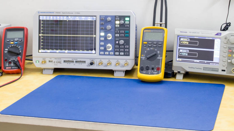
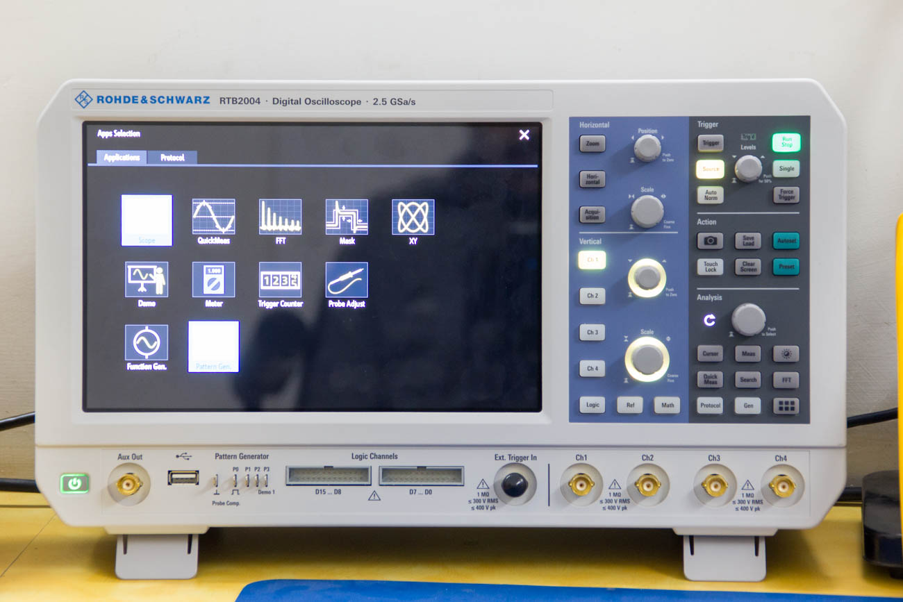
The scope arrived in a foam padded box with the accessories box at the top and the scope itself under it. The scope itself is quite light weight and fashions a huge screen which is the most obvious observation at first glance. The front panel has sufficient buttons and knobs however appropriate labels make them less intimidating to the first time user.
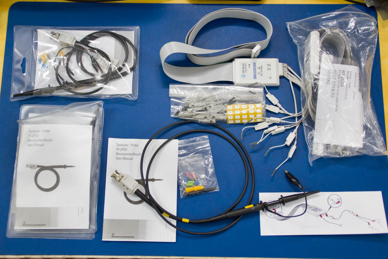
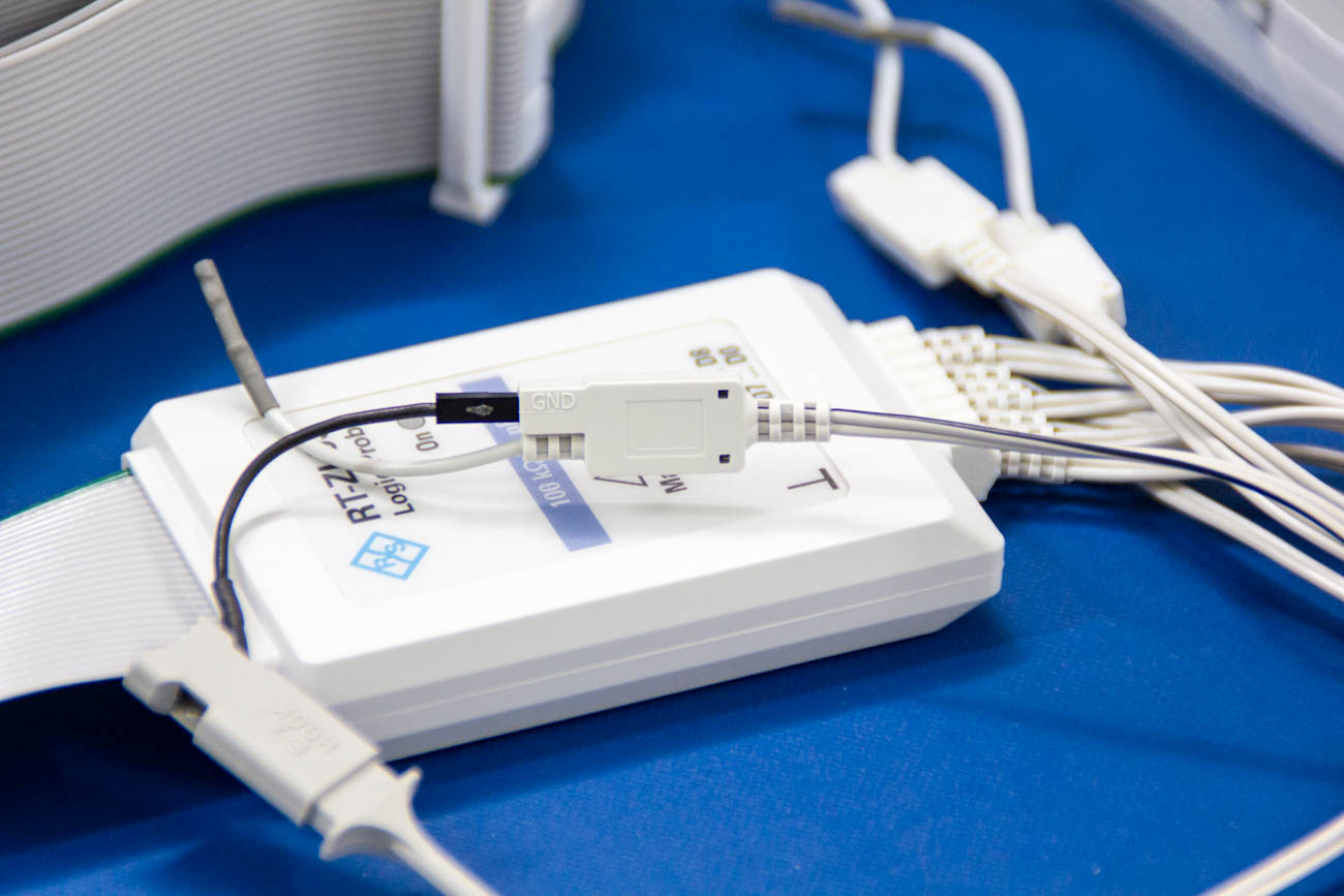
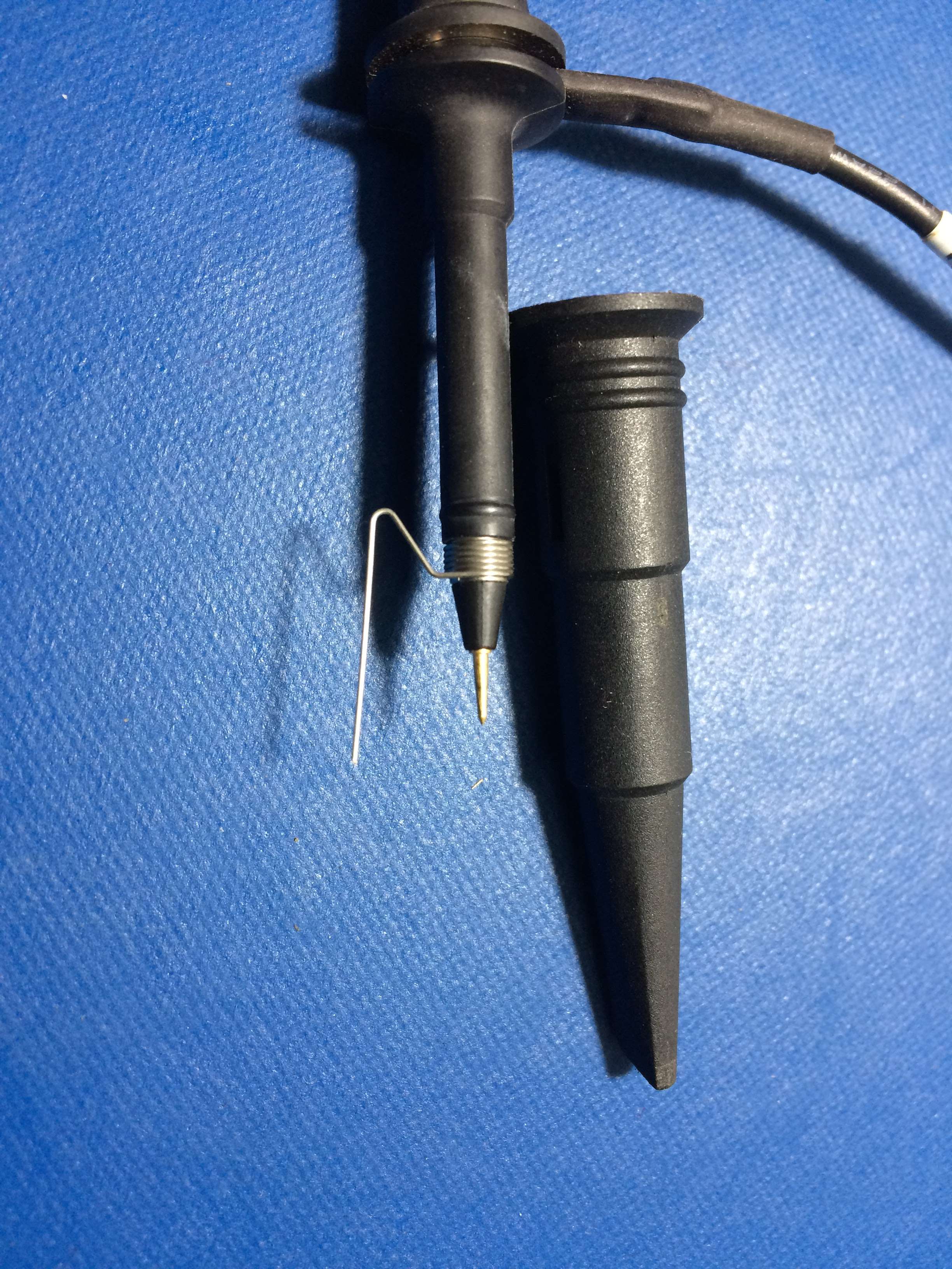
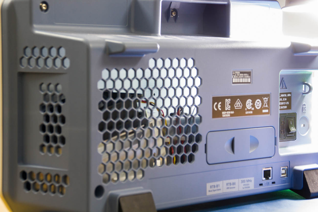
The kit comes with four 300 MHz probes, two 8-bit logic analyser cables and the usual knick-knacks like labels, color ferules and what not. The quality of the probes is great considering the price for them though one of my probes lost its springiness due to misuse I guess. Another missing item is the ground spring thingy that is shown in the picture below.
I did miss a carry case which is something that a scope of this price should be accompanied with. The front cover is for sale separately that will help protect the screen against accidental pokes and prods. The scope itself could have been thinner given that it is almost hollow on the inside.
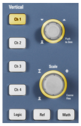
Another thing that bothers me is the absence of individual vertical controls for each channel. You have to press a button and then it selects the channel and then the knob works for that channel. The touch screen does a good job at covering up that part though using a mouse and keyboard was even simpler. I tried to use a wireless mouse and keyboard with the instrument which did not work so well. A wired mouse works well and an external VGA output would be brilliant if I ever need to connect an external monitor or projector to it.
Lastly, the glossy screen has been ridiculed enough so I will just add that a mat finish would have been better though not a total deal breaker.
Licenses and firmware
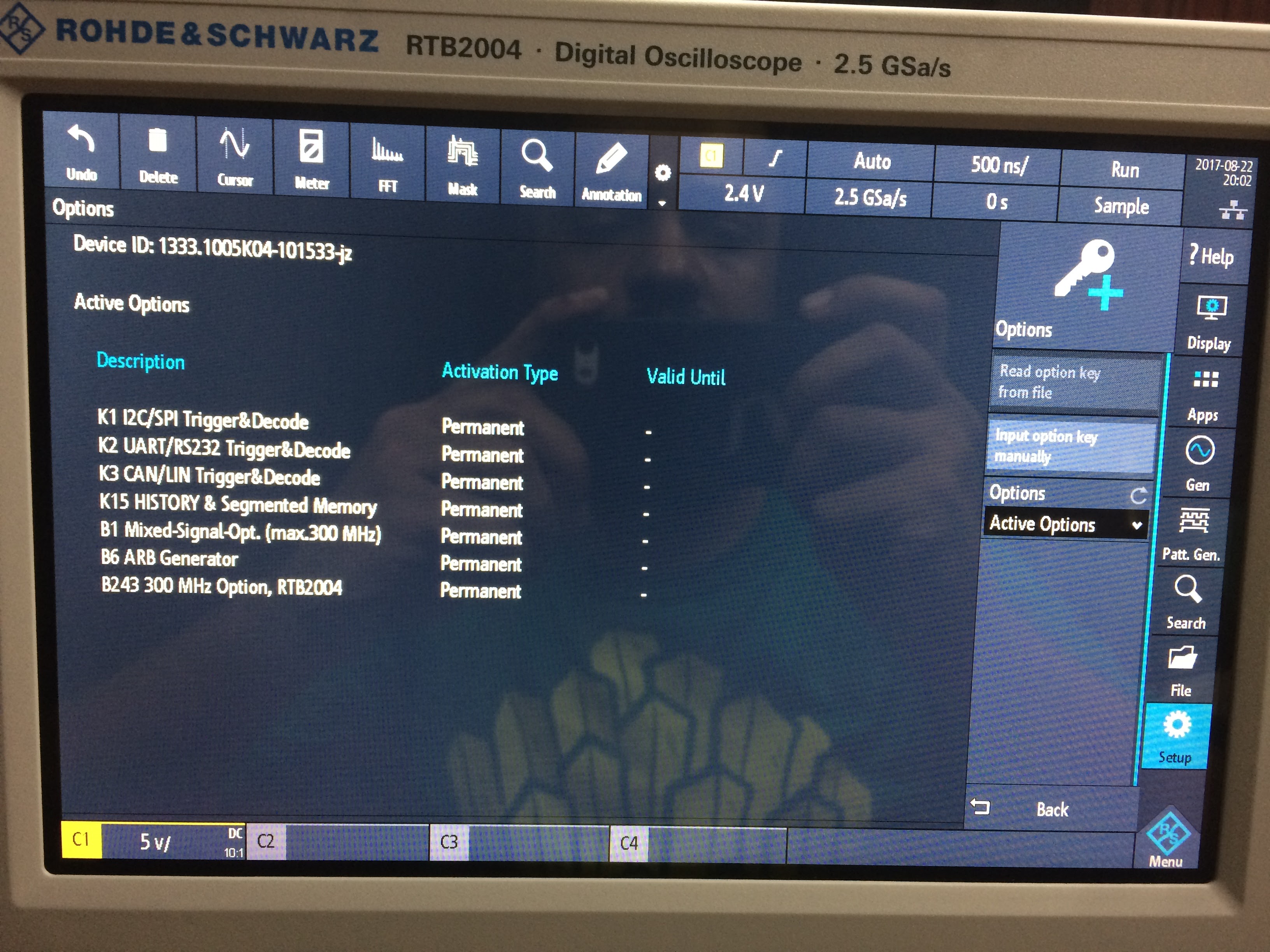
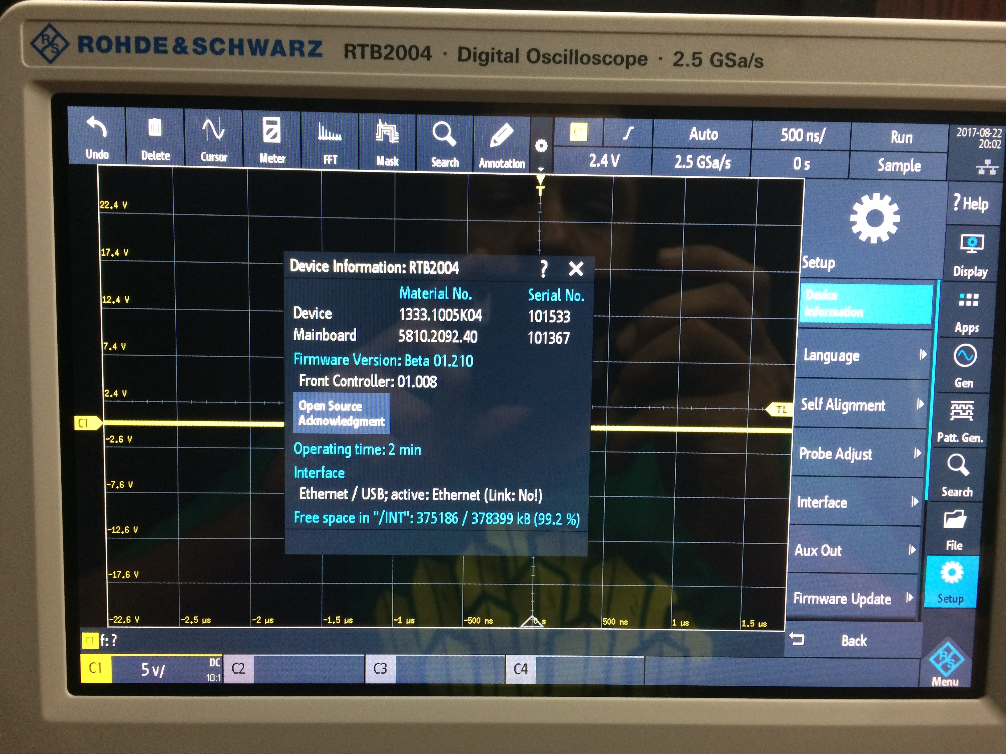
Figure 1 is a picture of the license details that my test unit came with. It is interesting to see a column for “Valid Until” which could mean some upgrades can be times based licenses. Another surprising fact was the presence of Beta firmware which leads me to believe that this particular unit was possibly a lab test piece. Figure 2 shows a picture of the relevant screen though I did upgrade the firmware just to be on the safe side before starting my tests.
Specification dive
The specifications are riddled with words such as memory depth, refresh rate and what not in addition to the traditional bandwidth, sample rate etc. The biggest issue for beginners in selecting a scope is wading through the fancy jargon and decipher patented names such as Keysight’s mega-zoom and the like. Lets take a quick look at some of the specs of the RTB and other offerings in the same segment.
| RTB | Keysight MSOX4041A | Tektronix MDO3034 | |
|---|---|---|---|
| Display size | 10.1” | 8.5” | 9” |
| Touchscreen | Yes | Yes | No |
| Warranty | 3Y | 3Y | 3Y |
| Memory | 10M points | 4M points | 10M points |
| ADC Res | 10-bit | 8-bit | 8-bit |
| Sample Rate | 1.25GS/s | 2.5GS/s | 2.5GS/s |
| BW | 300MHz | 350MHz | 350MHz |
| Refresh Rate | 50,000 Wfs/s | 1,000,000Wfs/s | 280,000Wfs/s |
| Price | $4760 | $10,144 | $10,000+ |
| Vertical Res | 1mV/Div | 1mv/Div | 1mv/Div |
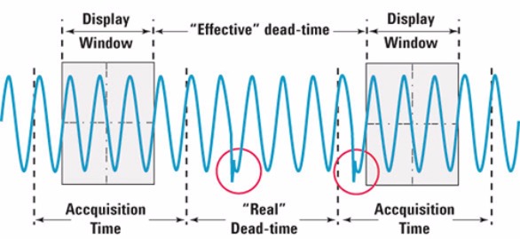
The Sampling rate is directly concerned with the ADC and is the rate at which the device can do the conversion. This however does not mean that it is what is always sampling. A digital scope needs to sample a given signal and will continue to do so until it runs out of memory. Once this happens, it must process the data and that takes a finite amount of time. This is analogous to dead-time or retrace time in analog scopes when the sawtooth wave would reset to minimum amplitude.
Memory depth is exactly what is says and is the amount of memory available to save the data. In the case of the RTB, it is 10 million samples which is huge however it also means that the scope will take longer to process all that data. In most cases this also translates to a larger signal length recorded in one go so even if you have spurious events that occur less frequently, it will get recorded within that long capture duration which is given as:
Measurement duration = memory depth/sampling frequency
Refresh rate corresponds to the number of times a scope can make successive readings. Again, if you take smaller samples, then the processing times go down and the refresh rate goes up.
[image: www.keysight.com]
The RTB has a high memory depth though it features the lowest refresh rate as well as sample rate. The real question is that does it make a difference? Well depends on the type of application you are working on. Keysight’s marketing flag waves the high refresh rate as the deciding factor and shows a demonstration of capturing an infrequent glitch reliability.
On the contrary, the price difference is phenomenal and if I can figure out a way to capture those infamous glitches, the RTB would be good as gold.
One thing that I have not gone into detail is the 10-bit ADC resolution which determines the number of vertical steps the instrument gets when capturing a signal. An 8-bit ADC results in 256 steps while a 10-bit one produces 1024 steps which is a 4 times the former. I was surprised to see the RTB have a 1 mv/division vertical resolution when some Rigol scopes already have a 0.5 mV/div scale. This can easily be corrected in software guys so get to it guys.
Signal Acquisition setup - Capture the glitch
In my first experiment, I need to capture a signal from my DUT which in this case is an Analog devices AD9850 in conjunction with an Arduino Nano. It is producing a fixed frequency sine wave with an occasional amplifier glitch that happens after three seconds. The idea is to capture the signal and possibly discover the glitch itself. My experiment starts with an auto set of the instrument followed by some manual exploration.
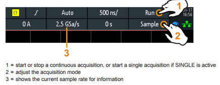
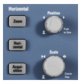
I was able to use the touch screen with much more convenience and ease than expected. Manually setting capture settings was as simple as pressing the Acquisition button on the front panel.
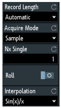
Leaving the Record lenght to automatic results in the system attempting to optimise the measurement based on the horizontal scale. There are a number of aquisition modes available which are explained in the manual as follows.
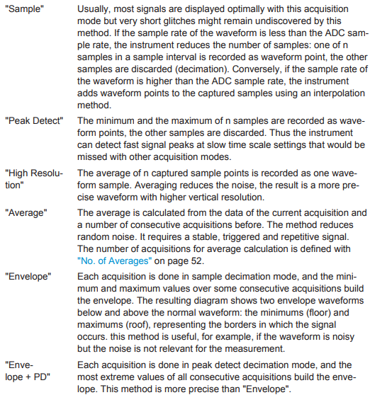
The sample mode is the usual method of capture but is not particularly effective for this experiment. For my signal, since the glitches vary in size and phase hence I resorted to using envelope mode along with a reduction in sample depth. The trigger frequency was measured using a second scope which saw a jump from 609Hkz to the kHz range and was able to record more data.

As seen from the spec table above the RTB has the lowest refresh rate of all though with a bit of manual tweaking, the shortcoming can be compensated for to a limit.
I imagine keysights higher refresh rate might be able to help with a faithful capture of such anomalies though the price tag would put a significant dent in one’s pocket.
I made a small video as shown below.
I addition to my little test, I was able to find this video on the Internet with the same scope and capturing glitches generated by a Keysight Scope. Would love comments on this.
The Bandwidth test
I would love to test out the 300MHz bandwidth on this lovely piece of machinery but am unable to. My function generator gave up on me for this test so until I get/buy a replacement device, I cannot really test the 3db roll off for this instrument. The in-built function generator doesn’t go up there so this part will have to wait.
Segmented Memory/History Mode and Nx Trigger
The standard process of capture and display allows a scope to display a triggering event on the screen however in cases where events are spurious and spaced apart, capturing is preferred using history mode. The typical segmented memory mode in a scope makes use of the fact that in certain cases, a signal line may have no events occurring on it. In the case of the RTB2K, the history segments mode helps capture larger sets of data over a given period but there are a few quirks to it.
There are two scenarios where history modes are effective.
a. When a glitch is to be recorded in a running system. The glitch or event is visible however we need to understand the data prior to the one in question.
b. When a boot up sequence is to be monitored and we require the first x samples for a sequence.
For experimentation, I used a STM32 Nucleo board running a simple piece of code to send data over a serial bus. It sends a count from 0 to 127 with each byte spaced a second apart.
The UART pin was connected to D0 on the digital IO and C1 on the Analog Channel and the memory depth was adjusted to 200K Samples. Then the protocol decoding was enabled and the triggering setup accordingly.
Next the DUT was allowed to run and once an event with two simultaneous bytes was detected, acquisition was stopped manually. Next using the history menu, I inspected the previous captures. The number of events in the memory could have been extended by setting the memory depth as desired though this was enough to demonstrate the history/segmented memory mode.
For the second use case, the acquisition menu was used set the number of Nx Samples to a desired number which in this case was 20. Once the Single Trigger button was pressed, the instrument began waiting for events to capture. The DUT was turned ON and the RTB2K began capturing instances of packets until 20 captures were complete. This list of 20 captures can be increased or decreased as per requirement and is an excellent method of monitoring initialisation signals in embedded systems.
On of the advantages that the RTB2K offers is the ability to vary the amount of capture memory depth and here is where the 10Mpt memory really shines. The history features comes at a cost though which I though was a little too much.
The Protocol Decoding test
Protocol decoding is not something new though the large memory discussed for the RTB2K makes the experience different than the traditional. The Rohde n Schwarz comes with the ability to decode a number of busses including UART, SPI, I2C and CAN/LIN . I have gone ahead and tested the UART in the previous section and will explore the I2C and SPI next.
I2C
I2C or as Atmel called it, TWI is a two wire protocol that uses one clock and one data line to enable communication between multiple devices. This simplifies things as the addressing allows for all devices to share the two bus wires. In my test, I used an 8051 based prototype that employs bit-bang technique to talk to a DS1307 which is an RTC chip. The idea is to verify if the software routine works as expected.
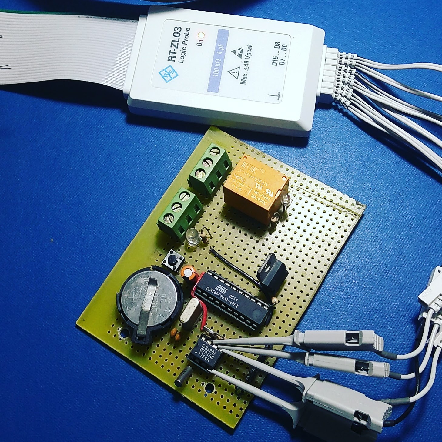
The module is over a decade old though it works without any issues. The first thing to do was to setup the channels and triggers and I used digital channels D0 for SCK and D1 for SDA. Triggering was set to start of frame condition and it worked perfectly. I was able to find a small glitch in the routine and though it does not effect the overall communication, it was good to identify a potential source of error. Here is a video demonstrating the use.
Debugging a bit-bang I2C bus using the Rohde n Schwarz RTB2K. The DUT is a light controller that has an 8051 that works as the master of the bus. Since it is a software implementation, there could be some issues with the signalling.
SPI and Search feature
Decoding SPI traffic is a tad bit different and for this experiment my setup was made up of an STM32F0 Nucleo board that makes use of the SPI peripheral. This experiment was a lot more fun and involved messing around with the signals a bit but I was able to setup decoding and triggering correctly.
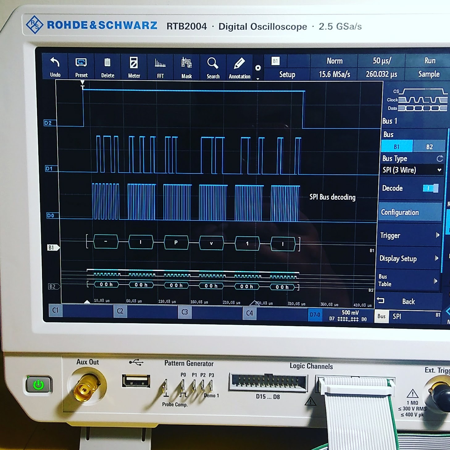
One feature that was useful was the ability to simultaneously decode two busses and in this case it would be 2 SPi channels; one for data coming out and the other for data going in. Additionally I was able to explore the search feature in the scope. The instrument allows the user to search through a capture segment, a particular pattern or combination of signals and their timing properties such as width etc. Check out the video below for a more detailed view of my experiment.
The decode option works great though I would have liked the ability to scan all history segments instead of one at a time. Still it is a great feature when used with the large memory depth.
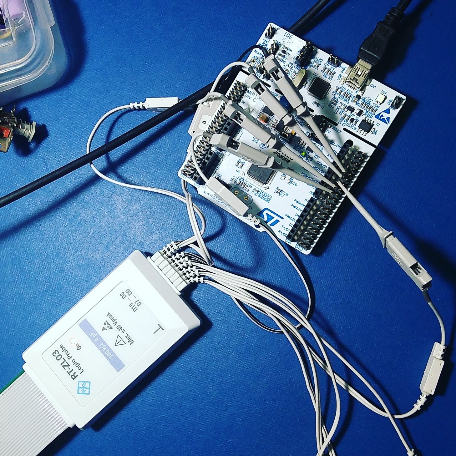
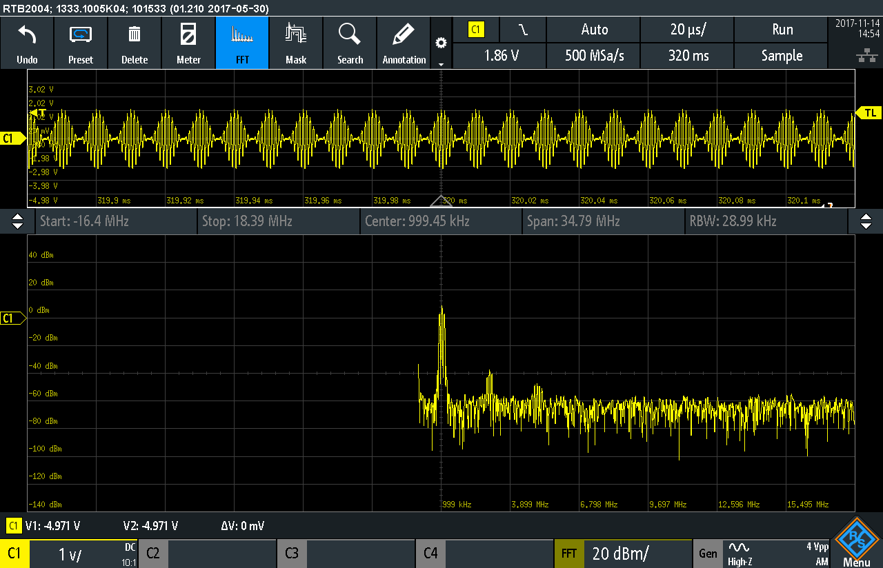
The FFT Test
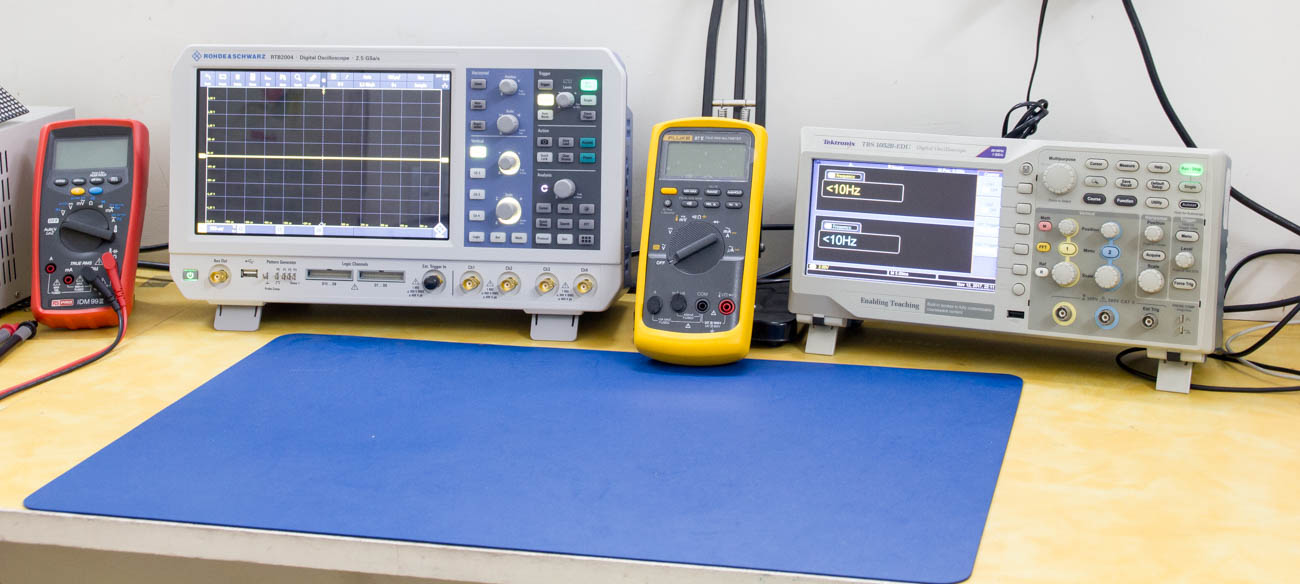
To evaluate the FFT function, I compared it to a Tek TBS1052 which is a 50MHz low cost teaching scope. The reason is that it has the best user experience and the RTB2K has too many options for simple tasks. My DUT was a cheap switching power supply which was connected a resistive load. The SMPS is expected to be full of harmonics and that was the point of the exercise.
I limited the bandwidth to 20MHz on both scopes and on the RTB2K, reduced the sample depth to the minimum. I was surprised to see a number of problems with the RTB which I am assuming will be rectified in future firmware releases.
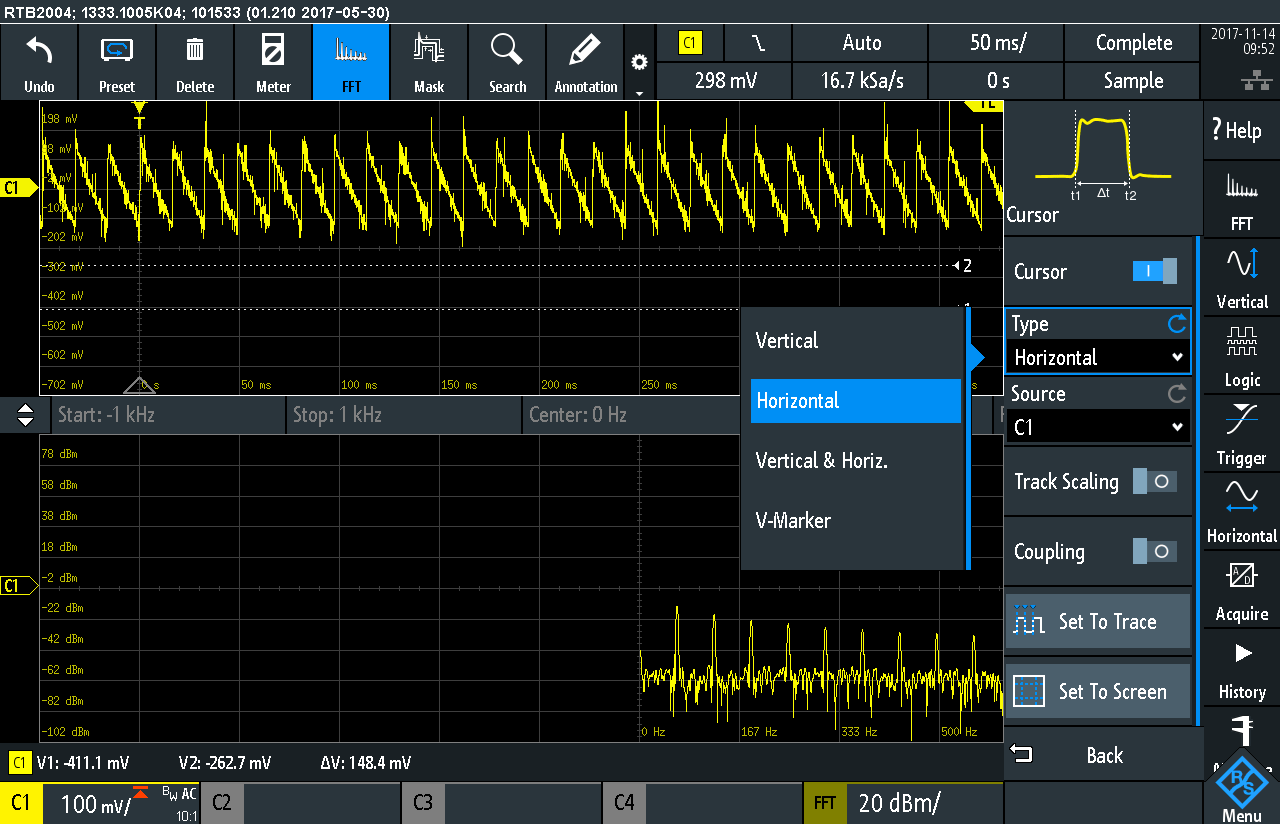
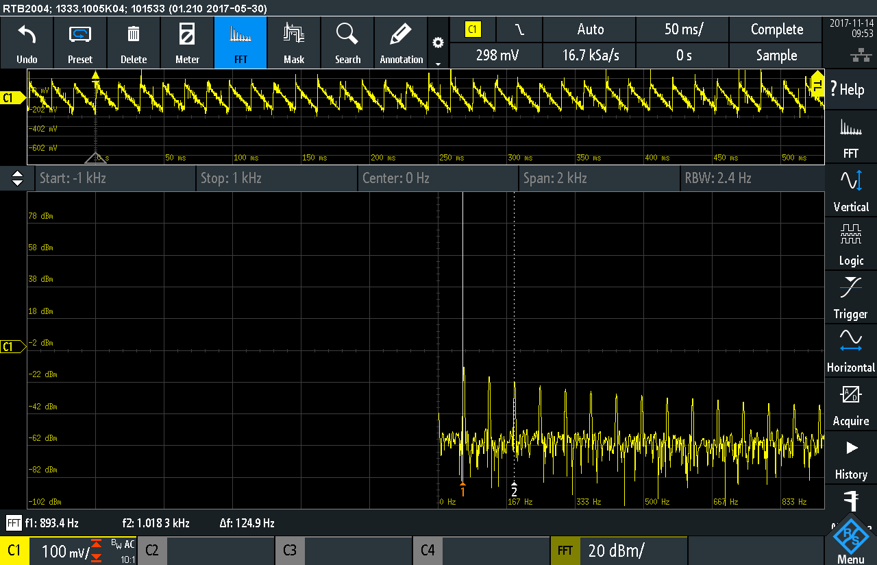
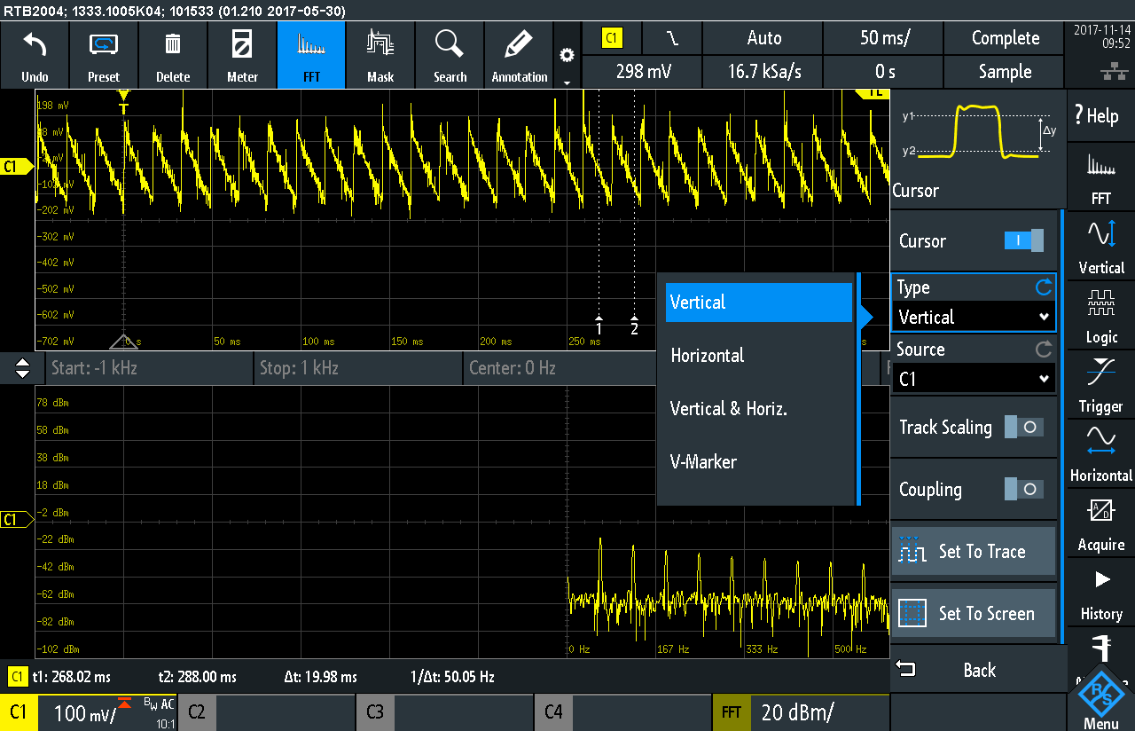
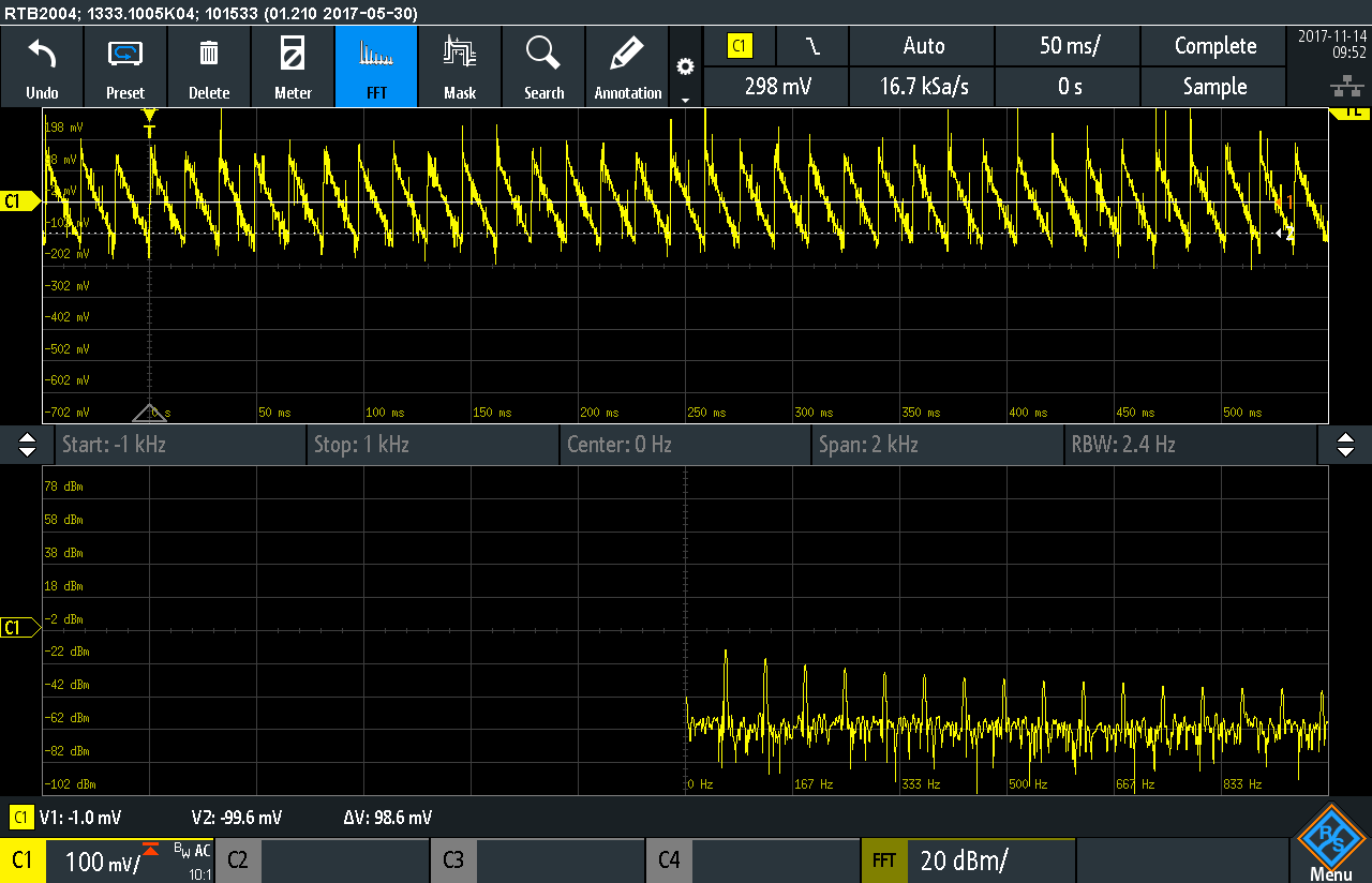
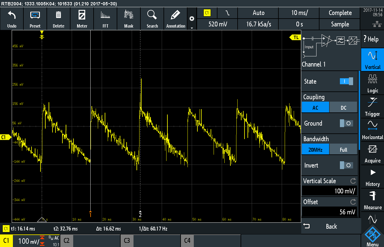
The first issues was when I enabled FFT for the first time. The two diagrams over lapped each other with little room for scale indicators. This is very confusing for the first time user and a serious bug if not declared as a feature. To rectify this, I had to drag the double arrow icon at the top to put both images in their respective containers.
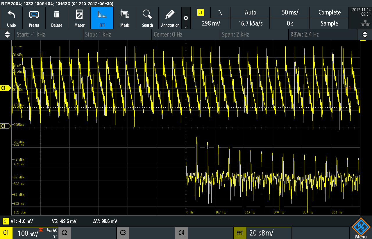
The second bug I found was in the cursors menu. Take a look at the screenshot and the cursor type description. The concept of vertical and horizontal cursors is confusing and Rohde and Schwarz would be just better off calling them time and amplitude cursors.
They show up incorrectly on the plots which is further cause for confusion.
The next bug is in the cursor position indicators themselves. Once the cursors were added, their values did not scale correctly to the actual graph(see the bottom left corner of the image). The situation was rectified only after I time scaled the plot once.
The FFT feature needs a bit of tuning and a little bit of understanding before you can start using it contrast to the Tek Scopes where a simple button press will take care of most things. It is a pity since it is one of the more used feature for me.
Touch screen and annotation
Yes it has a huge touch screen but its not always fun and games. My touch screen experience was a bit flunky where scrolling was not as responsive as expected and the plots kept jumping all over the place. I won’t comment on it more than that.
The annotation feature is quite handy though it only allows for a single text box to be placed on the screen. I would have like the ability to add multiple annotation boxes but its not a deal breaker.
Function generator
The function generator is a lot more capable than I thought. So instead of doing a dive into the function, I chose to experiment with a possible application which requires both the function generator as well as the scope. I have an RC low pass filter with R1 = 1K and C1 with one of two values; 0.1uF and 0.01uF.
The cut-off frequency for each case is 1.59kHz and 15.9kHz respectively which needs to be verified practically. I configured the function generator to produce a sine wave that sweeps from 1Hz to 20kHz incremented in a logarithmic fashion. This is done easily and it is clear that the output is attenuated at higher frequencies.
In order to plot the results in a Bode-plot manner, the acquisition menu has the option for a ‘chart-mode’ that allows a continuous time plot of the data as it comes in. Set to 1 seconds per division, both circuits were tested and the results are shown below.
The plot resembles a traditional Bode-plot and can be used for visual analysis thought the cut-off frequency is not indicated directly. One better method would be to connect it to LabView and do the analysis in software. For now, this experiment is shown in the video below.
And just to complete the evaluation, I went ahead and tried out the modulation output of the function generator. Combined with the FFT function, it becomes a handy tool for analysis and reporting.
Ethernet connectivity
The RTB2K comes with an in built web server which allows remote management of the device. This is an excellent feature which is useful when the instrument needs to be connected to a larger display for demonstration. You can use LabView to talk to the instrument as well though I was unable find demos that worked off the bat for the RTB2004.
Not much needs to be said about it other than it allows you to see the front panel of the instrument remotely. I must add that it was a much better experience than those clunky applications that came bundled with older scopes.
Concluding remarks
There is a lot I have not covered though this review is longer than I expected… and still going. I have one more thing that I want to include which i will add as an EDIT at the end once I am good and ready. For now, it is clear that the RTB2K needs some firmware updates, the most important of which is the the encoder thingy! Man it drives me crazy sometimes. I loved a lot of things about the scope which obviously includes the mammoth screen and the protocol decoding. The inability to connect a wireless mouse and keyboard combo was a big thing was me which was compensated for my the webserver and ethernet connectivity.
There are so many features that are really excellent such as the arbitrary function generator and sweep generator that make this scope great. Rohde n Schwarz, if you are reading this, then I want to request the addition of a Bode Plot Feature in the scope. If not, then at-least provide a Labview VI that allows us to do a VNA like analysis because that would make this scope brilliant.
Another firmware tweek I request is the addition of an additional vertical resolution step. The 10-bit ADC can go below the 1mV/div marker just like the Rigols in the market. Lastly, where is my carry case?
This piece of kit is replacing my other instruments and in style. The price positioning is fantastic and I love how the instrument performs and even though the complexity is a bit much for educational use, I woudl recommend it for any serious electronics workbench.