
Tutorial - Writing your own Serial Protocol using C
In this article, I take a look at designing and implementing a simple serial protocol using C. It can be used in microcontrollers or Single Board Computers
Description
Implementing a protocol in different languages takes different methodologies. This tutorial is an implementation of the TLV Protocol in Embedded C meant to be deployed on devices with low resources.
Details
A protocol is a predefined agreement and sequence of steps that is followed to send data from one point to the other over a medium of transmission. We talk to each other by sound and sight where one looks towards the person or calls out the name and then starts speaking. The same way electronic communication works and is the backbone of many systems today. In this article, I talk about designing, implementing and testing a simple communication protocol for use with microcontrollers and single board computers.
Existing protocols - A survey
Over the years, many big companies have come to create solutions for the communication problem. If you don’t already know the big names are UART, I2C/TWI, SPI, CAN, LIN are the most popular. Dedicated peripheral hardware blocks have been designed for these and are a part of modern microcontrollers like AVR, PIC and the list goes on. It is important to understand these existing standards before we start with our own experiment. In the proceeding section, I will explain the protocols in brief and complete details can be read in their respective specification documentation. I will also try to simplify the explanation to accelerate the process and if something comes out ’not right’ please leave a comment and I shall do the needful.
UART - Universal Serial Asynchronous Receive Transmit
There is a long history behind the UART and RS232 but simply put, its one of most used standard for transmitting digital data over short distances. It works by both the transmitter and receiver having pre-agreed speed of transmission. This speed is the bit rate, bits-per-second or baud rate and values range from 50bits/s to 460,800bits/s. What is important is the duration of each bit since the higher the speed, the smaller the pulse. Most commonly, 9600bps are use with simple/older microcontrollers and 115200bps are used with modern day devices.

Figure 1: UART Timing Diagram
Figure 1 taken from Wikipedia shows the timing diagram for a serial communications frame or one transaction. The communications line starts in high state and the transmitting device will hold the line low for one bit period. For 115200, this would be 8.68 µs and 9600bps, it would be 104.2 µs. Next the data bits are transmitted starting with the least significant bit and will end with a stop bit which return the line to high voltage. The voltage levels and EIA232 specifications are not important right now but it is sufficient to understand that one byte can be transmitted between two points in one transaction. For transmitting ‘hello world’ this process would repeat 11 times and the receiver will have to put the message in the right place.
The only disadvantage to this scheme is that the speed of communication is predefined. There are workarounds to this as well but that is beyond the scope of this document. Physically there is one wire for transmission and one for reception which means both devices can send and receive at the same time. Most common implementations have one-to-one communication however protocols such as MODBUS can be implemented on top of UART to aid with multi device communication. In this exercise, we will be implementing something similar since its simple and effective.
I2C/TWI
I²C (Inter-Integrated Circuit), pronounced I-squared-C, is a multi-master, multi-slave, packet switched, single-ended, serial computer bus invented by Philips Semiconductor (now NXP Semiconductors).link Unlike UART, I2C uses the same wire to send and receive however the speed of communication is variable. In a typical use-case, one device takes the role of master and its this device that generates the clock and decides the speed. The master also decides who to talk to and then the corresponding device will send a response.
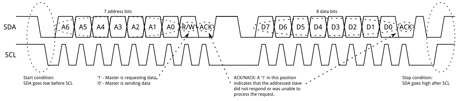
Figure 2 taken from spark fun.com shows the timing diagram for a typical I2c transaction. In essence, the master ‘asks’ for data and the slave ‘replies’.
Every device connected to these two wires or bus must have an address including the master(though not necessary). The master will first put the address on the wires which means more than one slave may be connected. Next comes a series of commands or command after which the slave will start to produce a reply the speed of which is governed by the master. Once the master has the required information, it creates signals to tell the slave to stop and in the eventuality that something bad occurs, the transaction will reset after a timeout post which a new transaction must start over.
The disadvantage is that since these transactions are more complicated, i.e. clock detection, start condition, stop condition, it’s always better to use a hardware peripheral. Most microcontrollers ship with an I2C controller which is capable of master mode and even have the ability to be configured as slave.
The reason why this article is being written in the first place is that we ran into a situation where I2C would not work. Boards such as the Intel Galileo, Edison etc will not function as I2C slaves and additionally, Texas Instruments, TI RTOS does not support I2C Slave for all devices… yet. I wanted to produce something that will be useful for everyone that uses these devices.
SPI
The Serial Peripheral Interface bus (SPI) is a synchronous serial communication interface specification used for short distance communication, primarily in embedded systems. Its one of the most widely used protocol with sensors given that its similar to UART however an additional clock line is used to control the speed of the data transfer. Additionally, select wires are used to control which device is being talked to which enables multi-device communication. Wiki Link


Figure 3 Shows a simple memory transfer scenario.
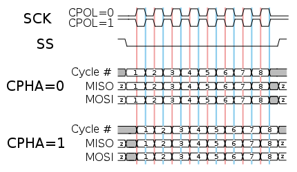
Figure 4 shows the simple nature of the transfer and though CPOL or polarity can complicate things, that discussion is beyond the scope of this document.
The disadvantage of this scheme is the extra number of pins required. Additionally, this method has very few constraints nor any inbuilt error checking etc. Its very useful for shot range sensor interfacing mainly.
CAN Bus and ModBUS
Just worth mentioning, are CAN and MODbus since these are application specific protocols and it would benefit the curious mind to read about these on their own. A detailed discussion would be of no use here and hence is beyond the scope of this document.
The Problem statement
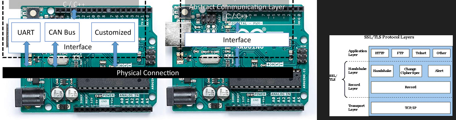
All of these protocols are different in some way. If an application demands a change from one of these protocols, it becomes even more obtuse. For example, if one wishes to use say TCP/IP or even MQTT which is a layer on top of TCP/IP, it would be difficult for everyone to be on the same page. In our case, since we have no hardware support for I2C slaves, we wish to use something like UART. This may be upgraded to MQTT in the future and this is our SRS or requirement.
Requirement: A protocol layer that can be used on microcontrollers and SBCs and can work on top of other hardware standards like UART, SPI and even TCP/IP. It should include support for multiple nodes and also have some basic error detection capabilities. It should be light and flexible.
This means, we need to start designing something on paper before we write the code.
The Design
This clearly is a protocol layer that will work on top of a signalling layer hence we need only describe data packaging and handling. We will need timeouts for failed transactions which could be optional and an addressing scheme to allow for multiple nodes. Lets being.
Addressing: 1 Byte should be enough since its not meant to be scalable. 1 byte for sender address as well in case we need it later. Size: 1 bytes should be enough to allow small frames. Payload: Since we are using 1 byte for frame size indication, the total payload should be less than 255 minus our overheads. Error checking: We will keep this lite on processing and use parity words. More details when we implement it.
To pack these lets add a start of frame and end of frame. Two bytes at the start- a character ‘:’ and ‘{‘ and ‘}’ at the end. If these are missing we will discard the frame.
The final frame will look like :{DEST SRC SIZE D0 D1 D2 … PARITY-WORD}
Thats good enough for the most part. Let not over think this and get right to designing the state machine.
Here is my version of the state diagram for the receive.
This diagram shows how the transactions will happen and the steps that the computer must follow. Some states may be merged in the final code however it is necessary to first draw out everything for the sake of understanding. Next comes the code.
Implementation
Depending upon the deployment platform, a user may choose his favourite language. For example, for hardware deployment as an IP Core, VHDL may be preferred or even Verilog. In my case the language will be C. This can be deployed on Microcontrollers, Linux and your favourite RTOS as well.
There are two ways to code a state machine where one method uses a Switch case statement and the other uses pointers to functions. I will be using the former for two reasons. Firstly, its easier for beginners to understand and this document is targeted towards beginners. Secondly, switch case code can be ported to VHDL as well and the same state machine may be synthesised in hardware after a few modifications.
The first step is to create an enumerated data type for the states to keep track of things.
1
enum state_codes {    wait, get_sof1, check_get_sof2, check_get_dest, check_get_src, get_size, setup_count, get_byte_dec, get_parity, get_eof, check_parity, write_data, discard_data } current_state, next_state;
We now have two variables called current_state and next_state to hold our values. To implement the functionality of each state, we can write individual functions but for now let code the main machine. The mechanics are simple- in every call or tick, do what the current_state should be doing. Hence we write a switch case statement as follows.
1
2
3
4
5
6
7
8
9
10
11
12
13
14
15
16
17
18
19
20
21
22
23
24
25
26
27
28
29
30
31
32
33
34
35
36
37
38
39
40
41
42
43
44
switch(current_state){

case wait:

        break;

case get_sof:

        break;
case check_get_sof2:

        break;
case check_get_dest:

        break;
case check_get_src:

        break;
case get_size:

        break;
case setup_count:

        break;
case get_byte_dec:

        break;
case get_parity:

        break;
case get_eof:

        break;
case check_parity:

        break;
case write_data:

        break;
case discard_data:

        break;
case default:
        break;
That is just a blank template and we will have to fill up what needs to be done next. The first state is wait which means that it will check for an event. Hence we need a mechanism of asynchronously managing events. Lets make another enumerated data type for that as well.
1
enum event_code { no_event, byte_received, error, timeout } current_event;
We need to write a function to inject events into the system and if you are really serious you should add a fifo as well. In this implementation, only one event is saved at a time which is OK for our case.
1
2
3
4
5
6
7
8
9
void event_set(enum event_code new_event){
    current_event=new_event;
}
void event_clear(void){
    current_event=no_event;
}
enum event_code event_get(void){
    return current_event;
}
These functions help to set, clear and retrieve events. Now back to our main machine. In the wait state, we check for a byte_received event so the code will be as follows:
1
2
3
4
5
6
7
8
9
case wait:
    switch(event_get()):
        case byte_received:
            next_state=get_sof1;
            break;
        case no_event, error, timeout:
            next_state=wait;
            break;
    break;
This means we have a switch case within a switch case which is confusing at times and you can do if then else if that’s something you like. The standard practice is the one shown and I use this techniques most often. Next we code the get_sof1 state. Now since we are on working with storing data we need a place as well. There are a number of ways to do this with the simplest being arrays. The downside is that the memory will always remain allocated and we don’t want that. So for the few bytes that are know, I usually like to go with dynamic memory allocation but for the sake of simplicity, I will use simple variables.
1
2
3
4
5
6
7
8
unsigned char sof1;
unsigned char sof2;
unsigned char dest_addr;
unsigned char src_addr;
unsigned char frame_size;
unsigned char parity1;
unsigned char eof1;
unsigned counter=0;
That takes care of some stuff when added to the start of the file. Global variables no less so lets tread carefully. The act of getting bytes from a buffer are encapsulated in a wrapper so that we may modify it later. For example, in the case of an 8051, serial data is stored in a register called SBUF. Lets write a function as:
1
2
3
unsigned char get_serial_buff(){
    return SBUF; // modify according to your hardware.
}
We use this as follows:
1
2
3
4
case get_sof1:
    sof1 = get_serial_buff();
    next_state = check_get_sof2;
    break;
We can check the SOF to be ‘:’ but this will not be possible if it were VHDL code. I preffer checking it either in a separate state or the next state.
1
2
3
4
5
6
7
case check_get_sof2:
    sof2=get_serial_buff();
    next_state = check_get_dest;
    if(sof1 != ‘:’){ // in case of error
        next_state = wait;
    }
    break;
Similarly we code the rest of the check-and-get state. Once we are sure that its the right address and we need to store the data, the fun part begins. We dynamically allocate the space using malloc and save the address in a pointer as:
1
2
3
4
5
6
7
unsigned char *ptr;

case setup_count:
    ptr=malloc( frame_size-7 );
    counter = 0;
    next_state =
    break;
Here the allocated memory is only for the data. Next we copy the data to the buffer.
1
2
3
4
5
6
7
8
9
case get_byte_dec:
    *(ptr+counter) = get_serial_buff();
    counter++;
    if ( counter>(frame_size-7) ){
        next_state= get_parity;
    } else {
        next_state = get_byte_dec;
    }
    break;
Once we have all the bytes, we check the parity and eof and pass on the pointer. There is still the matter of memory deallocation and updating states. Lets take a look at the code once completed.
1
2
3
4
5
6
7
8
9
10
11
12
13
14
15
16
17
18
19
20
21
22
23
24
25
26
27
28
29
30
31
32
33
34
35
36
37
38
39
40
41
42
43
44
45
46
47
48
49
50
51
52
53
54
55
56
57
58
59
60
61
62
63
64
65
66
67
68
69
70
71
72
73
74
75
76
77
78
79
80
81
82
83
84
85
86
87
88
89
90
91
92
93
94
95
96
97
98
99
100
101
102
103
104
105
106
107
108
109
110
111
112
113
114
115
116
117
118
119
120
121
const unsigned char MY_ADDRESS = 0x08; //Change this for your custom peripheral address
unsigned char sof1;
unsigned char sof2;
unsigned char dest_addr;
unsigned char src_addr;
unsigned char frame_size;
unsigned char parity1;
unsigned char eof1;
unsigned counter=0;
unsigned char *ptr;

enum state_codes {    wait, get_sof1, check_get_sof2, check_get_dest, check_get_src, get_size, setup_count, get_byte_dec, get_parity, get_eof, check_parity, write_data, discard_data } current_state, next_state;
enum event_code { no_event, byte_received, error, timeout } current_event;

void event_set(enum event_code new_event){
    current_event=new_event;
}
void event_clear(void){
    current_event=no_event;
}
enum event_code event_get(void){
    return current_event;
}

unsigned char get_serial_buff(){
    // return getch(); // for console testing on a hardware with a display.
    return SBUF; // modify according to your hardware.
}

void my_protocol_machine(){
    switch(current_state){
        case wait:
            switch(event_get()){
                case byte_received:
                    next_state=get_sof1;
                    break;
                case no_event, error, timeout:
                    next_state=wait;
                    event_set(no_event);
                    break;
            }
            break;
        case get_sof1:
            sof1 = get_serial_buff();
            next_state = check_get_sof2;
            break;
        case check_get_sof2:
            if(sof1 != ‘:’){ // in case of error
                next_state = wait;
                break;
            }
            sof2=get_serial_buff();
            next_state = check_get_dest;
            break;
        case check_get_dest:
            if( sof2 != ‘{‘ ){ // in case of error
                next_state = wait;
                break;
            }
            dest_addr = get_serial_buff();
            next_state = get_src;
            break;
        case check_get_src:
            if (dest_addr != MY_ADDRESS ){// wrong address?
                next_state = wait;
                break;
            }
            src_addr = get_serial_buff();
            break;
        case get_size:
            frame_size = get_serial_buff();
            next_state = setup_count;
            break;
        case setup_count:
            if( frame_size<=7 ){
                next_state = wait;
                break;
            }
            ptr=malloc( frame_size-7 );
            counter = 0;
            next_state = get_byte_dec;
            break;
        case get_byte_dec:
            *(ptr+counter) = get_serial_buff();
            counter++;
            if ( counter>(frame_size-7) ){
                next_state= get_parity;
            } else {
                next_state = get_byte_dec;
            }
            break;
        case get_parity:
            parity1 = get_serial_buff();
            next_state = get_eof;
            break;
        case get_eof:
             eof1 = get_serial_buff();
            next_state = check_parity;
            break;
        case check_parity:
            if( checkParity() > 0 ){
                next_state = write_data;
            } else {
                next_state = discard_data;
            }
            break;
        case write_data:
            // do something here
            next_state = wait;
            break;
        case discard_data, default:
            // check and deallocate memory here
            if ( ptr != null){
                free(ptr);
            }
            ptr = null;
            next_state = wait;
            break;
    }
    // do everything else here after the switch case including check for events
}
Now there are a few pieces missing. We need to access events to find if a time out has occurred. That is simply done by adding an event checker at the end of the switch case code. We also need to update the current state variable.
1
2
3
4
5
6
7
8
9
10
11
current_state = next_state; is added to the end of the code along with
if(next_state == wait){ // no need for a timer
    timer_stop();
} else {        // a valid state is next so restart the timing.
    reset_timer();
}

if( event_get() == timeout ){
    event_set(no_event);
    next_state = discard_data;
}
That’s it. We have a written a basic machine to get a chunk of data. The only thing missing is some writing data stuff. This I leave for now. You can printf it or send it or in my case I would memcpy it to a predefined pointer.
Lessons Learned
I think that is enough for this instalment but in the next article, I will test this code out, write another layer on this one so that I can really extract some information out of it in a format for my choice. This will be useful for sending floats and long type data over a stream. In a later article, I will do the same state machine using pointer and enumerated data types and lookup tables in C.
Let me know what you think because its a learning process and I want you to share a comment for my time.